Product Description
Introduction:
Linear guide is consisted of rail, block, rolling elements, retainer, recirculator, end seal etc. By using the rolling elements, such as balls or rollers between the rail and block, the linear guide can achieve high precision linear motion.Linear guide block is divied to flange type and square type without flange.or Seal type block, Standard type block, Double bearing type block, Short type block. Also,linear block is divided to high load capacity with standard block lenth and ultra high load capacity with longer block length.
Catalogue of Linear Xihu (West Lake) Dis.ways:
1.HG SERIES IS A HIGH ASSEMBLED BALL LINEAR XIHU (WEST LAKE) DIS. RAIL;
2.EG SERIES IS A LOW ASSEMBLED BALL LINEAR XIHU (WEST LAKE) DIS. RAIL;
3.RG SERIES IS A LINEAR XIHU (WEST LAKE) DIS. WITH ROLLERS ROLLER TPYE BLOCK,WHICH CAN AFFORD HIGH LOAD;
4.MGN/MGW SERIES IS A SMALL/MINIATURE LINEAR XIHU (WEST LAKE) DIS. RAIL.
Structure of Linear Xihu (West Lake) Dis.ways:
1.Rolling cycle system: slider, guide rail, end cover, steel ball, ball holder;
2.Lubrication system: oil nozzle and tubing joint;
3.Dust-proof system: oil scraper, negative dust seal dust-proof sheet, guide rail bolt cover, metal scrap
Advantages of Linear Xihu (West Lake) Dis.ways:
1.Easy to install ,direct locking with screw and worktable;
2.Design of the ball arrange to upgrade weight bearing capacity;
3.Long life with high speed,high accuracy and linear motion;
4.High speed, low noise;
5.High rigidity ,multiple precision
Applicable Industries:
Building Material Shops, Manufacturing Plant, Machinery Repair Shops, Retail, Printing Shops, Construction works , Advertising Company, Others.
Regular specifications as follows table:
|
HGHCA/HA Series |
HGLCA/HA Series |
HGWCC/HC Series |
|
HGH15CA/HGH15HA |
HGL15CA/HGL15HA |
HGW15CC/HGW15HC |
|
HGH20CA/HGH20HA |
HGL25CA/HGL25HA |
HGW20CC/HGW20HC |
|
HGH25CA/HGH25HA |
HGL30CA/HGL30HA |
HGW25CC/HGW25HC |
|
HGH30CA/HGH30HA |
HGL35CA/HGL35HA |
HGW30CC/HGW30HC |
|
HGH35CA/HGH35HA |
HGL45CA/HGL45HA |
HGW35CC/HGW35HC |
|
HGH45CA/HGH45HA |
HGL55CA/HGL55HA |
HGW45CC/HGW45HC |
|
HGH55CA/HGH55HA |
|
HGW55CC/HGW55HC |
|
HGH65CA/HGH65HA |
|
HGW65CC/HGW65HC |
Kindly pls contact service, if you have any problem, thank you!!!!!!!!!!!!!
/* January 22, 2571 19:08:37 */!function(){function s(e,r){var a,o={};try{e&&e.split(“,”).forEach(function(e,t){e&&(a=e.match(/(.*?):(.*)$/))&&1
| Application: | Warehouse Crane, Shipboard Crane, Goods Yard Crane, Medical Equipment, Automation Equipment, Building |
|---|---|
| Material: | Steel |
| Structure: | CNC |
| Samples: |
US$ 10/Piece
1 Piece(Min.Order) | Order Sample HG linear guide
|
|---|
| Customization: |
Available
|
|
|---|
.shipping-cost-tm .tm-status-off{background: none;padding:0;color: #1470cc}
|
Shipping Cost:
Estimated freight per unit. |
about shipping cost and estimated delivery time. |
|---|
| Payment Method: |
|
|---|---|
|
Initial Payment Full Payment |
| Currency: | US$ |
|---|
| Return&refunds: | You can apply for a refund up to 30 days after receipt of the products. |
|---|
What troubleshooting steps can be taken for common issues related to motor slide rail misalignment?
When dealing with motor slide rail misalignment, several troubleshooting steps can be taken to identify and resolve common issues. Here’s a detailed explanation:
Misalignment of motor slide rails can lead to various problems, including uneven movement, increased friction, excessive wear, and potential damage to the motor and slide rail components. Troubleshooting the issue involves a systematic approach to identify the cause of misalignment and take appropriate corrective actions. Here are some troubleshooting steps to consider:
1. Visual Inspection:
Begin by visually inspecting the motor slide rails and associated components. Look for any obvious signs of misalignment, such as visible gaps, skewed positioning, or uneven wear patterns. Check for loose or damaged mounting brackets, fasteners, or attachment points. Inspect the slide rails for any signs of damage, deformation, or excessive wear that may contribute to misalignment.
2. Measurement and Alignment:
Use precision measuring tools, such as calipers or laser alignment devices, to assess the alignment of the motor slide rails. Measure the distance between the slide rails at multiple points along their length to check for consistent spacing. Compare the measurements to the manufacturer’s specifications or alignment guidelines to identify any deviations. Adjust the positioning of the slide rails as necessary to achieve proper alignment.
3. Check Mounting Brackets and Fasteners:
Ensure that the mounting brackets and fasteners securing the motor slide rails are properly tightened. Loose brackets or fasteners can contribute to misalignment and instability. Carefully inspect the brackets and fasteners for any damage or wear that may affect their ability to maintain alignment. Tighten or replace any loose or damaged components as needed.
4. Lubrication and Friction:
Check the lubrication of the motor slide rails. Insufficient or improper lubrication can cause increased friction, leading to misalignment or uneven movement. Apply the appropriate lubricant according to the manufacturer’s recommendations. Ensure that the lubricant is evenly distributed along the slide rails and that any excess lubricant is removed to prevent accumulation of debris or contaminants.
5. Environmental Factors:
Consider environmental factors that may contribute to motor slide rail misalignment. Temperature extremes, humidity, dust, or vibration can affect the stability and alignment of the slide rails. If the environment poses challenges, consider implementing measures such as protective enclosures, seals, or vibration dampening to minimize the impact on alignment.
6. Professional Assistance:
If troubleshooting steps do not resolve the misalignment issue or if the cause is not apparent, it may be necessary to seek professional assistance. Contact the manufacturer or a qualified technician with expertise in motor slide rails for further diagnosis and guidance. They can provide specialized knowledge and tools to address complex misalignment issues.
In summary, troubleshooting misalignment issues with motor slide rails involves visual inspection, measurement, alignment adjustments, checking mounting brackets and fasteners, lubrication, considering environmental factors, and seeking professional assistance when needed. By systematically addressing these troubleshooting steps, it is possible to identify and resolve common issues related to motor slide rail misalignment, ensuring optimal performance and longevity of the motor system.
How do motor slide rails assist in the smooth and precise adjustment of motor positions?
Motor slide rails play a crucial role in facilitating the smooth and precise adjustment of motor positions. Here’s a detailed explanation:
Motor slide rails are designed to provide a guided and adjustable platform for mounting motors. They offer several features and mechanisms that aid in achieving smooth and precise motor position adjustments.
1. Sliding Mechanism:
Motor slide rails incorporate a sliding mechanism that allows the motor to move along the rail. This sliding mechanism can consist of ball bearings, rollers, or sliding surfaces with low friction. The smooth sliding action enables easy and effortless adjustment of the motor position. It ensures that the motor can be moved with minimal resistance, reducing the risk of jarring or jerky movements that could affect the motor’s stability or alignment.
2. Position Locking:
Motor slide rails often feature position locking mechanisms to secure the motor in a desired position once it has been adjusted. These locking mechanisms can include clamps, levers, or fasteners that hold the motor firmly in place. The position locking feature ensures that the motor remains stable and prevents unintended movement or shifting during operation. It helps maintain the precise motor position achieved, even when subjected to vibrations or external forces.
3. Graduated Scales and Markings:
Many motor slide rails are equipped with graduated scales or markings along the rail or the sliding component. These scales provide reference points and measurements that assist in achieving precise motor position adjustments. By aligning the motor with the appropriate markings, users can accurately position the motor to meet specific alignment requirements or desired positions. The graduated scales enable repeatability and consistency in motor adjustments, making it easier to replicate or fine-tune motor positions when needed.
4. Fine Adjustment Mechanisms:
Some motor slide rails incorporate fine adjustment mechanisms to facilitate precise positioning of the motor. These mechanisms can include micrometer screws, threaded rods, or precision adjustment knobs. They allow for incremental and controlled movements of the motor, enabling fine-tuning of the position with high accuracy. The fine adjustment mechanisms are particularly useful when precise motor alignment is critical, such as in applications requiring tight tolerances or when aligning the motor with other components or driven equipment.
5. Stiffness and Rigidity:
Motor slide rails are designed to provide stiffness and rigidity to support the motor and maintain its position. They are often constructed from materials such as steel or aluminum that offer high strength and resistance to bending or deformation. The stiffness of the slide rails ensures that the motor remains stable and doesn’t shift or vibrate excessively during operation. It contributes to the overall precision and reliability of motor position adjustments.
By combining these features and mechanisms, motor slide rails enable smooth and precise adjustment of motor positions. They provide a guided platform that allows for easy and controlled movement of the motor, while also ensuring stability and locking the motor in the desired position. The graduated scales, fine adjustment mechanisms, and stiffness of the slide rails further enhance the precision and repeatability of motor position adjustments.
In summary, motor slide rails assist in the smooth and precise adjustment of motor positions through their sliding mechanism, position locking features, graduated scales or markings, fine adjustment mechanisms, and stiffness. These attributes collectively contribute to the ease of use, accuracy, and reliability of motor slide rail systems in achieving the desired motor positions.
What materials are commonly used in the construction of durable and reliable motor slide rails?
In the construction of durable and reliable motor slide rails, several materials are commonly used. Here’s a detailed explanation:
1. Steel:
Steel is one of the most widely used materials for motor slide rails due to its excellent strength, durability, and load-bearing capabilities. Steel slide rails offer high rigidity and resistance to bending or deformation, ensuring stable and secure motor installations. Different types of steel, such as carbon steel or stainless steel, can be utilized based on the specific application requirements and environmental conditions.
2. Aluminum:
Aluminum is another popular material choice for motor slide rails, especially in applications where weight reduction is a consideration. Aluminum slide rails offer a good balance of strength and lightweight characteristics. They are corrosion-resistant, making them suitable for indoor and outdoor installations. Aluminum slide rails are commonly used in applications where weight reduction, ease of handling, and corrosion resistance are important factors.
3. Cast Iron:
Cast iron is known for its exceptional strength and durability, making it suitable for heavy-duty motor applications. Cast iron slide rails provide superior load-bearing capabilities and resistance to wear and tear. They are commonly used in industrial settings where robustness and longevity are crucial. Cast iron slide rails can withstand high loads and provide stability and rigidity for reliable motor positioning and alignment.
4. Stainless Steel:
Stainless steel slide rails offer excellent corrosion resistance, making them ideal for applications where exposure to moisture, chemicals, or harsh environments is a concern. Stainless steel is highly durable, resistant to rust and staining, and can withstand high loads. These properties make stainless steel slide rails suitable for a wide range of industries, including food processing, pharmaceuticals, marine, and outdoor applications.
5. Engineering Plastics:
Certain engineering plastics, such as acetal (polyoxymethylene) or nylon, are used in the construction of motor slide rails. These materials offer good mechanical properties, such as low friction, high wear resistance, and self-lubricating characteristics. Engineering plastic slide rails are lightweight, corrosion-resistant, and can provide smooth and quiet operation. They are often utilized in applications where noise reduction, chemical resistance, or lightweight construction is desired.
6. Composite Materials:
Composite materials, such as fiberglass-reinforced plastic (FRP), are used in some motor slide rails. These materials offer a combination of strength, rigidity, and corrosion resistance. Composite slide rails are lightweight, non-conductive, and can provide excellent resistance to chemicals and environmental factors. They are commonly used in applications where weight reduction, electrical insulation, or resistance to corrosive substances is important.
The selection of materials for motor slide rails depends on various factors, including the specific application requirements, load capacities, environmental conditions, and desired performance characteristics. Manufacturers consider these factors to choose the most suitable material that ensures durability, reliability, and optimal performance of the motor slide rail system.
In summary, commonly used materials in the construction of durable and reliable motor slide rails include steel, aluminum, cast iron, stainless steel, engineering plastics, and composite materials. Each material has its specific advantages and is chosen based on factors such as strength, durability, load-bearing capacity, corrosion resistance, weight reduction, and environmental considerations.


editor by CX 2024-05-03
China manufacturer OEM/ODM Customize Hgw35 CNC Linear Guide Linear Guide Way35mm Rail with Stepper Motor vacuum pump oil
Product Description
Introduction:
Linear guide is consisted of rail, block, rolling elements, retainer, recirculator, end seal etc. By using the rolling elements, such as balls or rollers between the rail and block, the linear guide can achieve high precision linear motion.Linear guide block is divied to flange type and square type without flange.or Seal type block, Standard type block, Double bearing type block, Short type block. Also,linear block is divided to high load capacity with standard block lenth and ultra high load capacity with longer block length.
Catalogue of Linear Xihu (West Lake) Dis.ways:
1.HG SERIES IS A HIGH ASSEMBLED BALL LINEAR XIHU (WEST LAKE) DIS. RAIL;
2.EG SERIES IS A LOW ASSEMBLED BALL LINEAR XIHU (WEST LAKE) DIS. RAIL;
3.RG SERIES IS A LINEAR XIHU (WEST LAKE) DIS. WITH ROLLERS ROLLER TPYE BLOCK,WHICH CAN AFFORD HIGH LOAD;
4.MGN/MGW SERIES IS A SMALL/MINIATURE LINEAR XIHU (WEST LAKE) DIS. RAIL.
Structure of Linear Xihu (West Lake) Dis.ways:
1.Rolling cycle system: slider, guide rail, end cover, steel ball, ball holder;
2.Lubrication system: oil nozzle and tubing joint;
3.Dust-proof system: oil scraper, negative dust seal dust-proof sheet, guide rail bolt cover, metal scrap
Advantages of Linear Xihu (West Lake) Dis.ways:
1.Easy to install ,direct locking with screw and worktable;
2.Design of the ball arrange to upgrade weight bearing capacity;
3.Long life with high speed,high accuracy and linear motion;
4.High speed, low noise;
5.High rigidity ,multiple precision
Applicable Industries:
Building Material Shops, Manufacturing Plant, Machinery Repair Shops, Retail, Printing Shops, Construction works , Advertising Company, Others.
Regular specifications as follows table:
|
HGHCA/HA Series |
HGLCA/HA Series |
HGWCC/HC Series |
|
HGH15CA/HGH15HA |
HGL15CA/HGL15HA |
HGW15CC/HGW15HC |
|
HGH20CA/HGH20HA |
HGL25CA/HGL25HA |
HGW20CC/HGW20HC |
|
HGH25CA/HGH25HA |
HGL30CA/HGL30HA |
HGW25CC/HGW25HC |
|
HGH30CA/HGH30HA |
HGL35CA/HGL35HA |
HGW30CC/HGW30HC |
|
HGH35CA/HGH35HA |
HGL45CA/HGL45HA |
HGW35CC/HGW35HC |
|
HGH45CA/HGH45HA |
HGL55CA/HGL55HA |
HGW45CC/HGW45HC |
|
HGH55CA/HGH55HA |
|
HGW55CC/HGW55HC |
|
HGH65CA/HGH65HA |
|
HGW65CC/HGW65HC |
Kindly pls contact service, if you have any problem, thank you!!!!!!!!!!!!!
/* January 22, 2571 19:08:37 */!function(){function s(e,r){var a,o={};try{e&&e.split(“,”).forEach(function(e,t){e&&(a=e.match(/(.*?):(.*)$/))&&1
| Application: | Warehouse Crane, Shipboard Crane, Goods Yard Crane, Medical Equipment, Automation Equipment, Building |
|---|---|
| Material: | Steel |
| Structure: | CNC |
| Samples: |
US$ 10/Piece
1 Piece(Min.Order) | Order Sample HG linear guide
|
|---|
| Customization: |
Available
|
|
|---|
.shipping-cost-tm .tm-status-off{background: none;padding:0;color: #1470cc}
|
Shipping Cost:
Estimated freight per unit. |
about shipping cost and estimated delivery time. |
|---|
| Payment Method: |
|
|---|---|
|
Initial Payment Full Payment |
| Currency: | US$ |
|---|
| Return&refunds: | You can apply for a refund up to 30 days after receipt of the products. |
|---|
Where can individuals find reliable information about choosing, installing, and maintaining motor slide rails?
When seeking reliable information about choosing, installing, and maintaining motor slide rails, individuals can refer to various sources. Here’s a detailed explanation:
1. Manufacturer’s Documentation and Websites:
The manufacturer of the motor slide rails is often the best source of information. They provide detailed documentation, product catalogs, technical specifications, and installation guides specific to their motor slide rail products. Manufacturers’ websites are valuable resources, offering comprehensive information about their product range, features, and maintenance recommendations. Individuals can access datasheets, user manuals, and frequently asked questions (FAQs) to gain insights into choosing the right motor slide rails and their proper installation and maintenance.
2. Industry Associations and Trade Organizations:
Industry associations and trade organizations related to the specific application or industry where motor slide rails are used can provide valuable information. These organizations often publish technical resources, guidelines, and best practices related to motor slide rails. They may also organize conferences, seminars, or webinars where individuals can learn about the latest developments in motor slide rail technology and maintenance techniques.
3. Online Forums and Communities:
Online forums and communities focused on engineering, industrial automation, or specific applications can be helpful sources of information. Platforms such as engineering discussion boards, Reddit communities, or specialized forums allow individuals to ask questions, share experiences, and seek advice from industry professionals, enthusiasts, and experts. Participating in these communities can provide valuable insights into the selection, installation, and maintenance of motor slide rails.
4. Technical Publications and Journals:
Technical publications and journals in the field of engineering, automation, or mechanical systems often feature articles, case studies, and research papers related to motor slide rails. These publications provide in-depth analysis, comparisons, and evaluations of different motor slide rail technologies, installation techniques, and maintenance practices. Scientific databases and online libraries can be searched for relevant publications in the form of articles, white papers, or conference proceedings.
5. Consulting with Experts and Suppliers:
Consulting with experts in the field, such as engineers, technicians, or consultants specializing in motor systems, can provide personalized guidance and recommendations. These professionals have practical experience and knowledge about motor slide rails and can offer insights into the selection, installation, and maintenance processes. Additionally, suppliers or distributors of motor slide rails may have technical support teams that can provide assistance and recommendations based on their expertise.
6. Training Courses and Workshops:
Training courses and workshops organized by manufacturers, industry associations, or educational institutions can provide structured learning opportunities. These programs cover topics such as motor slide rail selection, installation techniques, and maintenance best practices. Attending these training sessions allows individuals to acquire knowledge directly from industry experts and gain hands-on experience in working with motor slide rails.
In summary, individuals can find reliable information about choosing, installing, and maintaining motor slide rails through manufacturer’s documentation and websites, industry associations and trade organizations, online forums and communities, technical publications and journals, consulting with experts and suppliers, as well as training courses and workshops. By utilizing these diverse sources of information, individuals can make informed decisions and ensure the proper selection, installation, and maintenance of motor slide rails for their specific needs.
Can motor slide rails accommodate various motor mounts and couplings?
Yes, motor slide rails are designed to accommodate various motor mounts and couplings. Here’s a detailed explanation:
Motor slide rails are versatile components that can be integrated into motor installations with different types of motor mounts and couplings. They are designed to provide a universal platform for mounting motors, allowing for flexibility and compatibility with a wide range of motor configurations.
1. Motor Mounting Options:
Motor slide rails are typically designed with multiple mounting options to accommodate different motor mounts. These mounting options can include slots, holes, or threaded inserts that allow for the attachment of various motor mounting brackets or plates. The flexibility in motor mounting options enables the use of different motor mount designs, such as foot mounts, flange mounts, or face mounts. Motor slide rails provide a secure and adjustable interface for connecting the motor mounts to the rail system.
2. Coupling Compatibility:
Motor slide rails can also accommodate various types of motor couplings. Motor couplings are used to connect the motor shaft to the driven equipment, such as a gearbox or a load-bearing mechanism. Different types of couplings, such as flexible couplings, rigid couplings, or torsionally flexible couplings, have specific dimensional requirements and attachment methods. Motor slide rails are designed to provide sufficient space and clearance for the installation of different types of motor couplings. They allow for easy integration of the coupling components, ensuring proper alignment and connection between the motor and the driven equipment.
3. Adjustable Mounting Positions:
One of the key advantages of motor slide rails is their adjustable mounting positions. They provide a range of positions along the rail where the motor can be secured. This adjustability allows for fine-tuning the motor position and aligning it with the driven equipment or other components in the system. The ability to adjust the motor position using the slide rails accommodates variations in motor mount dimensions and facilitates precise alignment of the motor and coupling.
4. Customization and Adaptability:
In some cases, motor slide rails can be customized or adapted to specific motor mount or coupling requirements. Manufacturers may offer options for modifying the dimensions, hole patterns, or attachment methods of the slide rails to suit unique motor mounting or coupling configurations. This customization ensures compatibility and ease of integration with specialized motor systems or applications.
Overall, motor slide rails are designed to be versatile and adaptable, allowing for the accommodation of various motor mounts and couplings. The multiple mounting options, compatibility with different coupling types, adjustable mounting positions, and potential for customization make motor slide rails a flexible solution for motor installations across a wide range of industries and applications.
In summary, motor slide rails are capable of accommodating various motor mounts and couplings. Their design incorporates multiple mounting options, compatibility with different coupling types, adjustable mounting positions, and potential for customization, ensuring versatility and compatibility with different motor configurations.
What is the purpose of motor slide rails in the context of electric motor installations?
In the context of electric motor installations, motor slide rails serve several important purposes. Here’s a detailed explanation:
1. Easy Motor Installation and Removal:
Motor slide rails provide a convenient and efficient method for installing and removing electric motors. These rails are typically mounted on a motor base or mounting platform and allow the motor to slide in and out smoothly. By using motor slide rails, the motor can be easily positioned and secured in place during installation, and later removed for maintenance or replacement without the need for complex disassembly.
2. Precise Motor Alignment:
Motor slide rails facilitate precise motor alignment with the driven equipment. They allow for horizontal adjustment, ensuring that the motor shaft is parallel and co-linear with the driven shaft. This alignment is crucial for optimal performance, minimizing energy losses, and reducing wear and tear on both the motor and the driven equipment. Motor slide rails offer the flexibility to make fine adjustments to achieve the desired alignment, resulting in improved efficiency and reliability.
3. Vibration Damping and Noise Reduction:
Motor slide rails help dampen vibrations generated by electric motors during operation. Vibrations can arise from factors such as motor imbalances, misalignment, or external forces. The use of slide rails with vibration-dampening properties or by incorporating additional vibration isolation mechanisms can reduce the transmission of vibrations to the surrounding structure. This dampening effect improves overall system performance, reduces noise levels, and protects other components from excessive vibrations.
4. Maintenance and Service Accessibility:
Motor slide rails provide easy access to the motor for maintenance and service tasks. By sliding the motor along the rails, technicians can quickly reach various motor components, such as bearings, cooling fans, or electrical connections, for inspection, lubrication, or repairs. This accessibility simplifies routine maintenance procedures, reduces downtime, and improves the overall serviceability of the motor.
5. Flexibility for Motor Positioning:
Motor slide rails offer flexibility in motor positioning within the installation. They allow for adjustments in the motor’s position, both horizontally and vertically, to accommodate specific space constraints or align with existing equipment. This flexibility is particularly beneficial when retrofitting motors into existing systems or when dealing with limited space. Motor slide rails enable customization of the motor’s position to optimize performance and ensure compatibility with the application requirements.
6. Load Distribution and Stability:
Motor slide rails contribute to load distribution and stability in electric motor installations. The rails help distribute the weight of the motor evenly across the mounting platform, preventing excessive stress on specific points. This load distribution improves the overall stability of the motor and reduces the risk of structural damage or misalignment caused by uneven weight distribution.
In summary, motor slide rails serve the purpose of facilitating easy motor installation and removal, enabling precise motor alignment, dampening vibrations, providing accessibility for maintenance and service tasks, offering flexibility in motor positioning, and contributing to load distribution and stability. By utilizing motor slide rails effectively, electric motor installations can achieve improved performance, reduced downtime, and enhanced overall reliability.
editor by CX 2024-04-24
China manufacturer Linear Stage Actuator Slide Guide Rail Module CNC Ball Screw Xy Motion Table NEMA 11 Stepper Motor Heavy Load Router vacuum pump
Product Description
NEMA11 stepper motor electric dc motor for 3d printer
General Specification:
| Item | Specifications |
| Step Angle | 1.8° |
| Temperature Rise | 80ºCmax |
| Ambient Temperature | -20ºC~+50ºC |
| Insulation Resistance | 100 MΩ Min. ,500VDC |
| Dielectric Strength | 500VAC for 1minute |
| Shaft Radial Play | 0.02Max. (450g-load) |
| Shaft Axial Play | 0.08Max. (450g-load) |
| Max. radial force | 28N (20mm from the flange) |
| Max. axial force | 10N |
Products of special request can be made according to the customer request !
Our Company offers 3 major series of products:Hybrid Stepper motors, Brushless Dc motor and Dc Brush motor.
We are always continues develop new type models.If you need other kinds of parts, please don’t hesitate to contact us.
Amy Gao
/* January 22, 2571 19:08:37 */!function(){function s(e,r){var a,o={};try{e&&e.split(“,”).forEach(function(e,t){e&&(a=e.match(/(.*?):(.*)$/))&&1
| Application: | Universal, Industrial, Household Appliances, Car, Power Tools |
|---|---|
| Operating Speed: | Adjust Speed |
| Excitation Mode: | Compound |
| Function: | Run |
| Casing Protection: | Protection Type |
| Number of Poles: | 8 |
| Samples: |
US$ 25/Piece
1 Piece(Min.Order) | |
|---|
| Customization: |
Available
|
|
|---|
Are motor slide rails suitable for use with both AC and DC electric motors?
Yes, motor slide rails are suitable for use with both AC and DC electric motors. Here’s a detailed explanation:
Motor slide rails are mechanical components designed to support and guide the movement of motors in various applications. They are typically used to facilitate linear motion, allowing motors to be positioned or moved along a defined path. The compatibility of motor slide rails with AC and DC electric motors is primarily determined by the mechanical specifications and requirements of the specific motor and application.
The fundamental function of motor slide rails is to provide a stable and controlled movement mechanism for motors. This function is independent of the type of electric motor used, whether it is an AC motor or a DC motor. The key considerations when using motor slide rails with electric motors are related to the mechanical aspects rather than the electrical characteristics of the motors.
When selecting motor slide rails for use with electric motors, several factors need to be considered:
1. Load Capacity and Size:
The motor slide rails should be chosen based on the load capacity and size requirements of the electric motor. The rails should be able to support the weight of the motor and any additional loads. It is important to consider the size and dimensions of both the motor and the slide rails to ensure proper fit and compatibility.
2. Mounting and Integration:
The mounting and integration of the motor slide rails with the electric motor should be carefully evaluated. The slide rails should be compatible with the motor mounting brackets or any other components involved in the motor installation. Proper alignment and secure attachment of the motor to the slide rails are essential for safe and reliable operation.
3. Environmental Considerations:
The operating environment and conditions should also be taken into account when selecting motor slide rails for use with electric motors. Factors such as temperature, humidity, dust, or exposure to chemicals may affect the materials and performance of the slide rails. It is important to choose slide rails that are suitable for the specific environmental conditions in which the motor will operate.
Overall, motor slide rails can be used with both AC and DC electric motors as long as the mechanical specifications and requirements of the motors are taken into consideration. The compatibility of the slide rails with the electric motors is primarily determined by factors such as load capacity, size, mounting, integration, and environmental considerations. By selecting appropriate slide rails and ensuring proper installation, users can effectively utilize motor slide rails with both AC and DC electric motors in various applications.
Can motor slide rails contribute to reducing vibrations and noise associated with motor operation?
Yes, motor slide rails can contribute to reducing vibrations and noise associated with motor operation. Here’s a detailed explanation:
Motor slide rails play a role in minimizing vibrations and noise by providing stability, dampening vibrations, and reducing mechanical resonance. Here are the ways in which motor slide rails can help in reducing vibrations and noise:
1. Stability and Rigidity:
Motor slide rails offer a stable and rigid platform for mounting the motor. The rigid structure helps in minimizing vibrations by providing a secure and immobile base for the motor. It prevents excessive movement or oscillation of the motor, reducing the generation of vibrations that can propagate through the system and cause noise.
2. Vibration Dampening:
Motor slide rails can incorporate features or materials that help dampen vibrations. They can be designed with vibration-absorbing materials, such as rubber or elastomers, integrated into the rail system. These materials absorb and dissipate vibrations, reducing their transmission to other components and minimizing the associated noise.
3. Shock Absorption:
Some motor slide rails are equipped with shock-absorbing mechanisms or dampers. These mechanisms are designed to absorb sudden shocks or impacts that may occur during motor operation. By absorbing shocks, the slide rails help reduce the vibrations that can be generated from such events, thereby reducing noise levels.
4. Vibration Isolation:
In applications where vibrations from the motor can adversely affect sensitive components or nearby equipment, motor slide rails can be used for vibration isolation. Vibration isolation mounts or pads can be integrated between the motor slide rails and the mounting surface. These mounts are designed to absorb and isolate vibrations, preventing their transmission to the surrounding environment and minimizing noise generation.
5. Resonance Reduction:
Motor slide rails can help mitigate mechanical resonance, which is a phenomenon that can amplify vibrations and noise. Resonance occurs when the natural frequency of the motor or the system matches the excitation frequency, resulting in increased vibrations. By providing a rigid and well-supported mounting platform, motor slide rails can help shift the natural frequencies away from the excitation frequencies, reducing the likelihood of resonance and minimizing the associated noise.
6. Vibration Analysis and Optimization:
Motor slide rails can be used in conjunction with vibration analysis and optimization techniques to further reduce vibrations and noise. By monitoring and analyzing the vibration characteristics of the motor system, adjustments can be made to the mounting position, alignment, or other parameters to minimize vibrations. Motor slide rails with adjustable features and fine-tuning mechanisms allow for precise positioning and alignment, facilitating the optimization process.
Overall, while motor slide rails alone may not completely eliminate vibrations and noise associated with motor operation, they can significantly contribute to reducing their impact. The stability and rigidity provided by the slide rails, along with vibration dampening features, shock absorption, vibration isolation, and resonance reduction capabilities, help in minimizing vibrations and noise propagation. Combined with vibration analysis and optimization techniques, motor slide rails can help achieve a quieter and more vibration-free motor operation.
In summary, motor slide rails can contribute to reducing vibrations and noise associated with motor operation through stability, vibration dampening features, shock absorption, vibration isolation, resonance reduction, and their compatibility with vibration analysis and optimization techniques.
Can motor slide rails be used for both horizontal and vertical motor installations?
Yes, motor slide rails can be used for both horizontal and vertical motor installations. Here’s a detailed explanation:
Motor slide rails are versatile components that provide flexibility in motor positioning and alignment. They are designed to accommodate various installation orientations, including both horizontal and vertical configurations. The adaptability of motor slide rails allows them to be used in different orientations to suit the specific requirements of the motor and application.
Horizontal Motor Installations:
In horizontal motor installations, the motor slide rails are typically mounted on a base or mounting platform. The motor is then positioned on the rails and secured in place. Horizontal motor installations are commonly used in applications where the motor shaft needs to be parallel and co-linear with the driven equipment. The motor slide rails facilitate precise alignment, allowing for horizontal adjustability to achieve the desired alignment. Horizontal motor installations are prevalent in many industrial and commercial applications.
Vertical Motor Installations:
In vertical motor installations, the motor slide rails are used to support and position the motor vertically. The rails are mounted vertically on a base or mounting structure, and the motor is slid into position along the rails. Vertical motor installations are typically employed in applications where space is limited, and it is more practical or efficient to position the motor vertically. Vertical motor installations are common in situations such as pump systems, hoists, or machinery where a compact footprint is desired.
Motor slide rails designed for vertical installations may have additional features to ensure the motor’s stability and secure placement. These features can include locking mechanisms, anti-vibration pads, or other components to prevent the motor from shifting or rotating while in operation.
Whether used for horizontal or vertical motor installations, motor slide rails offer several benefits. They allow for easy motor installation and removal, precise alignment, vibration damping, maintenance accessibility, and flexibility in motor positioning. Their versatility in accommodating different installation orientations makes them suitable for a wide range of applications, providing the necessary adaptability to meet specific motor and system requirements.
In summary, motor slide rails can be used for both horizontal and vertical motor installations. They are designed to provide flexibility and ease of use in positioning and aligning motors, regardless of the installation orientation. The choice between horizontal and vertical installation depends on the specific application, space constraints, and the desired alignment and performance objectives.
editor by CX 2024-04-10
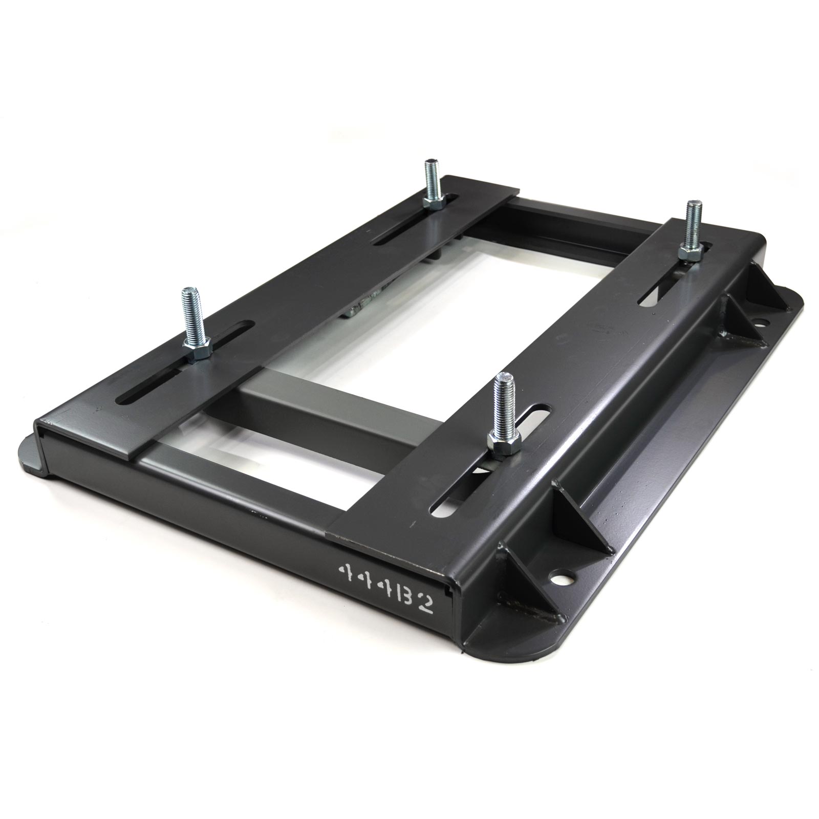
China OEM Hot Selling SMA 210 270 Adjustable Motor Slide Base and 312/6.8 DHA Motor Rail vacuum pump adapter
Product Description
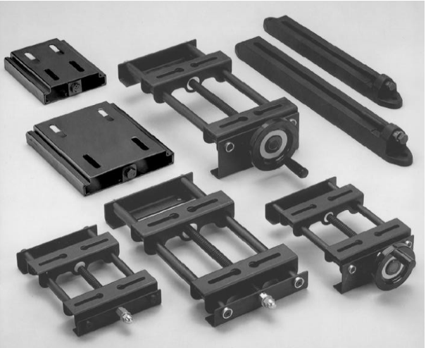
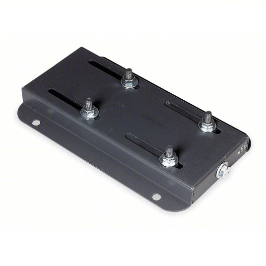
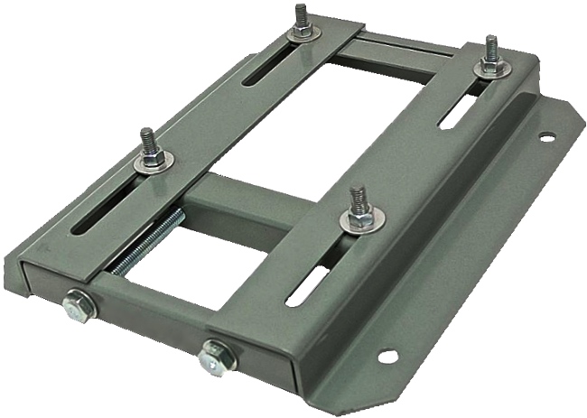
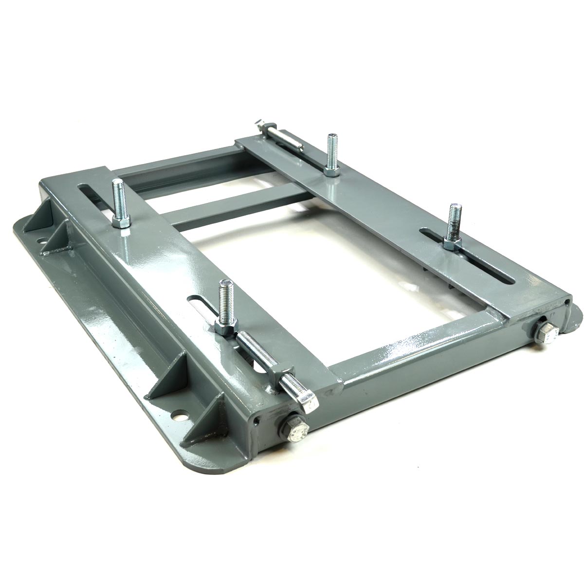
SMA Common Base:
Characleristics: galvanization finish, with split platesslidling, it’s convenient for bolts fixing of motors.
Application: fixing and adjustment of all series motors.
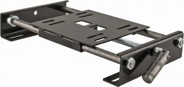
MP Motor Base:
Characteristics: gavanization fnish WTH MONOPLATE SLIDNG,bending and pressing
Applcatiorne the HangZhoug and adjustment of large power motors.
MB Type Motor Pedestal:
Characteristics: welded with high quality steel, powder coating finish, with matched fixing screw ofmotors, it is much convenient for fixing and adjustment.
Application: Application: suitable for the fixing and adjustment of large,medium and small power motors.
DHA Motor Rail:
it is with unique design, beautiful appearance, steady fixing and powerful weight bearing. It can be widely uesd in the fixing and adjustment of different kinds of motors.
characteristics:
Made of high quality steel with pressing and processing. It is with matched fixing screw of motor, much convenient for adjustment.
Application: the fixing and adjustment of different kinds of motors.
Main Products:
Timing belt pulleys, timing bars, timing belt clamping plates.
Shaft locking devices (assemblies) and shrink discs: could be alternative for Ringfeder, Sati, Chiaravalli, BEA, KBK, Tollok, etc.
V belt pulleys and taper lock bush.
Sprockets, idler, and plate wheels.
Gears and racks: spur gear, helical gear, bevel gear, pinion gear, worm gear, gear rack.
Shaft couplings: miniature coupling, curved tooth coupling, chain coupling, HRC coupling, normex coupling, FCL coupling, GE coupling, rigid and flexible coupling, jaw coupling, disc coupling, multi-beam coupling, universal joint, torque limiter, shaft collars.
Forging, Casting, Stamping Parts.
Other customized power transmission products and Machining Parts (OEM).
/* January 22, 2571 19:08:37 */!function(){function s(e,r){var a,o={};try{e&&e.split(“,”).forEach(function(e,t){e&&(a=e.match(/(.*?):(.*)$/))&&1
| Standard or Nonstandard: | Standard |
|---|---|
| Feature: | Flame-Retardant, Anti-Static, Oil-Resistant, Cold-Resistant, Corrosion-Resistant, Skid-Resistance, Wear-Resistant, Acid-Resistant |
| Application: | Motor |
| Surface Treatment: | Zinc Plating |
| Material: | Carbon Steel |
| Standard: | European Standard |
| Samples: |
US$ 10/Piece
1 Piece(Min.Order) | |
|---|
| Customization: |
Available
|
|
|---|
What troubleshooting steps can be taken for common issues related to motor slide rail misalignment?
When dealing with motor slide rail misalignment, several troubleshooting steps can be taken to identify and resolve common issues. Here’s a detailed explanation:
Misalignment of motor slide rails can lead to various problems, including uneven movement, increased friction, excessive wear, and potential damage to the motor and slide rail components. Troubleshooting the issue involves a systematic approach to identify the cause of misalignment and take appropriate corrective actions. Here are some troubleshooting steps to consider:
1. Visual Inspection:
Begin by visually inspecting the motor slide rails and associated components. Look for any obvious signs of misalignment, such as visible gaps, skewed positioning, or uneven wear patterns. Check for loose or damaged mounting brackets, fasteners, or attachment points. Inspect the slide rails for any signs of damage, deformation, or excessive wear that may contribute to misalignment.
2. Measurement and Alignment:
Use precision measuring tools, such as calipers or laser alignment devices, to assess the alignment of the motor slide rails. Measure the distance between the slide rails at multiple points along their length to check for consistent spacing. Compare the measurements to the manufacturer’s specifications or alignment guidelines to identify any deviations. Adjust the positioning of the slide rails as necessary to achieve proper alignment.
3. Check Mounting Brackets and Fasteners:
Ensure that the mounting brackets and fasteners securing the motor slide rails are properly tightened. Loose brackets or fasteners can contribute to misalignment and instability. Carefully inspect the brackets and fasteners for any damage or wear that may affect their ability to maintain alignment. Tighten or replace any loose or damaged components as needed.
4. Lubrication and Friction:
Check the lubrication of the motor slide rails. Insufficient or improper lubrication can cause increased friction, leading to misalignment or uneven movement. Apply the appropriate lubricant according to the manufacturer’s recommendations. Ensure that the lubricant is evenly distributed along the slide rails and that any excess lubricant is removed to prevent accumulation of debris or contaminants.
5. Environmental Factors:
Consider environmental factors that may contribute to motor slide rail misalignment. Temperature extremes, humidity, dust, or vibration can affect the stability and alignment of the slide rails. If the environment poses challenges, consider implementing measures such as protective enclosures, seals, or vibration dampening to minimize the impact on alignment.
6. Professional Assistance:
If troubleshooting steps do not resolve the misalignment issue or if the cause is not apparent, it may be necessary to seek professional assistance. Contact the manufacturer or a qualified technician with expertise in motor slide rails for further diagnosis and guidance. They can provide specialized knowledge and tools to address complex misalignment issues.
In summary, troubleshooting misalignment issues with motor slide rails involves visual inspection, measurement, alignment adjustments, checking mounting brackets and fasteners, lubrication, considering environmental factors, and seeking professional assistance when needed. By systematically addressing these troubleshooting steps, it is possible to identify and resolve common issues related to motor slide rail misalignment, ensuring optimal performance and longevity of the motor system.
What considerations should be taken into account when selecting motor slide rails for a specific application?
When selecting motor slide rails for a specific application, several considerations should be taken into account. Here’s a detailed explanation:
1. Load Capacity:
One of the primary considerations is the load capacity of the motor slide rails. The slide rails should be able to support the weight and forces exerted by the motor and any additional components or loads attached to it. It’s important to determine the maximum load that the slide rails will be subjected to in the specific application and choose rails with an appropriate load rating to ensure safe and reliable operation.
2. Travel Distance and Stroke Length:
The required travel distance or stroke length of the motor slide rails is another important factor to consider. The slide rails should be able to accommodate the desired range of movement for the motor, allowing for the necessary adjustments and positioning within the application. It’s crucial to select slide rails with a stroke length that meets the specific requirements of the application, taking into account any space limitations or operational constraints.
3. Mounting Compatibility:
Consider the compatibility of the motor slide rails with the existing mounting configuration in the application. Check whether the slide rails can be easily integrated with the motor mounts, brackets, or plates used in the system. Ensure that the mounting options and hole patterns of the slide rails align with the motor’s mounting requirements to facilitate a secure and proper attachment.
4. Dimensional Requirements:
Evaluate the dimensional requirements of the motor slide rails in relation to the available space and constraints in the application. Consider the overall length, width, and height of the slide rails to ensure they can fit within the designated installation area. It’s important to account for any clearance requirements, surrounding components, or spatial limitations that may impact the selection of slide rail dimensions.
5. Environmental Factors:
Take into account the environmental conditions in which the motor slide rails will operate. Consider factors such as temperature, humidity, exposure to dust or contaminants, and potential vibrations or shocks. Ensure that the selected slide rails are designed to withstand and perform reliably in the specific environmental conditions of the application. Look for features such as corrosion resistance, sealing or protective coatings, and robust construction that can enhance the durability and longevity of the slide rails.
6. Precision and Accuracy:
If precise motor positioning is critical for the application, consider the level of precision and accuracy required from the slide rails. Some applications may demand high repeatability and tight tolerances in motor adjustments. In such cases, look for slide rails that offer fine adjustment mechanisms, graduated scales, or other features that enable precise positioning and alignment of the motor.
7. Application-Specific Requirements:
Consider any specific requirements or challenges posed by the application. This could include factors such as speed requirements, duty cycles, special safety considerations, or unique industry-specific standards. Ensure that the selected motor slide rails meet these specific requirements and comply with relevant standards or regulations.
By considering these factors, you can make an informed decision when selecting motor slide rails for a specific application. It’s important to balance the technical requirements, environmental conditions, and application-specific factors to choose slide rails that provide optimal performance, reliability, and longevity within the intended application.
In summary, when selecting motor slide rails for a specific application, considerations should include load capacity, travel distance, mounting compatibility, dimensional requirements, environmental factors, precision and accuracy needs, and any application-specific requirements or challenges.
Can motor slide rails be used for both horizontal and vertical motor installations?
Yes, motor slide rails can be used for both horizontal and vertical motor installations. Here’s a detailed explanation:
Motor slide rails are versatile components that provide flexibility in motor positioning and alignment. They are designed to accommodate various installation orientations, including both horizontal and vertical configurations. The adaptability of motor slide rails allows them to be used in different orientations to suit the specific requirements of the motor and application.
Horizontal Motor Installations:
In horizontal motor installations, the motor slide rails are typically mounted on a base or mounting platform. The motor is then positioned on the rails and secured in place. Horizontal motor installations are commonly used in applications where the motor shaft needs to be parallel and co-linear with the driven equipment. The motor slide rails facilitate precise alignment, allowing for horizontal adjustability to achieve the desired alignment. Horizontal motor installations are prevalent in many industrial and commercial applications.
Vertical Motor Installations:
In vertical motor installations, the motor slide rails are used to support and position the motor vertically. The rails are mounted vertically on a base or mounting structure, and the motor is slid into position along the rails. Vertical motor installations are typically employed in applications where space is limited, and it is more practical or efficient to position the motor vertically. Vertical motor installations are common in situations such as pump systems, hoists, or machinery where a compact footprint is desired.
Motor slide rails designed for vertical installations may have additional features to ensure the motor’s stability and secure placement. These features can include locking mechanisms, anti-vibration pads, or other components to prevent the motor from shifting or rotating while in operation.
Whether used for horizontal or vertical motor installations, motor slide rails offer several benefits. They allow for easy motor installation and removal, precise alignment, vibration damping, maintenance accessibility, and flexibility in motor positioning. Their versatility in accommodating different installation orientations makes them suitable for a wide range of applications, providing the necessary adaptability to meet specific motor and system requirements.
In summary, motor slide rails can be used for both horizontal and vertical motor installations. They are designed to provide flexibility and ease of use in positioning and aligning motors, regardless of the installation orientation. The choice between horizontal and vertical installation depends on the specific application, space constraints, and the desired alignment and performance objectives.
editor by CX 2024-03-27
China Custom Hot Sale 530/10/12 DHA Slide Guide Motor Rail for 132/10 Motor Type vacuum pump for ac
Product Description
SMA Common Base:
Characleristics: galvanization finish, with split platesslidling, it’s convenient for bolts fixing of motors.
Application: fixing and adjustment of all series motors.
MP Motor Base:
Characteristics: gavanization fnish WTH MONOPLATE SLIDNG,bending and pressing
Applcatiorne the HangZhoug and adjustment of large power motors.
MB Type Motor Pedestal:
Characteristics: welded with high quality steel, powder coating finish, with matched fixing screw ofmotors, it is much convenient for fixing and adjustment.
Application: Application: suitable for the fixing and adjustment of large,medium and small power motors.
DHA Motor Rail:
it is with unique design, beautiful appearance, steady fixing and powerful weight bearing. It can be widely uesd in the fixing and adjustment of different kinds of motors.
characteristics:
Made of high quality steel with pressing and processing. It is with matched fixing screw of motor, much convenient for adjustment.
Application: the fixing and adjustment of different kinds of motors.
Main Products:
Timing belt pulleys, timing bars, timing belt clamping plates.
Shaft locking devices (assemblies) and shrink discs: could be alternative for Ringfeder, Sati, Chiaravalli, BEA, Tollok, etc.
V belt pulleys and taper lock bush.
Sprockets, idler, and plate wheels.
Gears and racks: spur gear, helical gear, bevel gear, pinion gear, worm gear, gear rack.
Shaft couplings: miniature coupling, curved tooth coupling, chain coupling, HRC coupling, normex coupling, FCL coupling, GE coupling, rigid and flexible coupling, jaw coupling, disc coupling, multi-beam coupling, universal joint, torque limiter, shaft collars.
Forging, Casting, Stamping Parts.
Other customized power transmission products and Machining Parts (OEM).
/* January 22, 2571 19:08:37 */!function(){function s(e,r){var a,o={};try{e&&e.split(“,”).forEach(function(e,t){e&&(a=e.match(/(.*?):(.*)$/))&&1
| Standard or Nonstandard: | Standard |
|---|---|
| Feature: | Flame-Retardant, Anti-Static, Oil-Resistant, Cold-Resistant, Corrosion-Resistant, Skid-Resistance, Wear-Resistant, Acid-Resistant |
| Application: | Motor |
| Surface Treatment: | Zinc Plating |
| Material: | Carbon Steel |
| Standard: | European Standard |
| Samples: |
US$ 10/Piece
1 Piece(Min.Order) | |
|---|
| Customization: |
Available
|
|
|---|
How does the selection of motor slide rails impact the overall performance and longevity of motors?
The selection of motor slide rails has a significant impact on the overall performance and longevity of motors. Here’s a detailed explanation:
The motor slide rails play a crucial role in supporting and guiding the movement of motors in various applications. The selection of appropriate slide rails directly affects the performance, efficiency, and lifespan of motors. Here are some key factors to consider:
1. Precision and Accuracy:
The selection of motor slide rails with high precision and accuracy is essential for achieving smooth and precise motor movement. Slide rails with tight tolerances and minimal play minimize backlash and vibration, resulting in improved motor performance. Precise slide rails ensure accurate positioning of the motor, which is critical in applications that require precise control or alignment. Choosing slide rails with high precision can enhance the overall performance and reliability of motors.
2. Load Capacity:
The load capacity of motor slide rails is an important consideration to ensure that the rails can support the weight of the motor and any additional loads. Using slide rails with insufficient load capacity can lead to premature wear, excessive deflection, or even failure of the rails, resulting in compromised motor performance and potential safety hazards. It is crucial to select slide rails that can handle the anticipated load requirements to maintain optimal motor performance and longevity.
3. Durability and Materials:
The durability and materials of motor slide rails directly impact their longevity and ability to withstand demanding operating conditions. Slide rails made from high-quality materials, such as stainless steel or aluminum alloys, offer better resistance to corrosion, wear, and environmental factors. Additionally, slide rails with appropriate surface treatments or coatings can provide enhanced protection against abrasion, chemicals, or extreme temperatures. Choosing durable slide rails ensures long-term performance and reliability of motors, especially in applications with harsh environments or heavy usage.
4. Friction and Lubrication:
The selection of motor slide rails with appropriate friction characteristics and lubrication requirements is crucial for optimizing motor performance and longevity. Excessive friction between the slide rails and motor can result in increased energy consumption, reduced efficiency, and accelerated wear. Conversely, insufficient friction may lead to instability or inadequate load support. The type and amount of lubrication required for the slide rails should be considered to minimize friction, reduce wear, and maintain smooth operation. Proper lubrication practices help extend the lifespan of both the slide rails and the motor.
5. Environmental Considerations:
The operating environment can significantly impact the performance and longevity of motors and slide rails. Factors such as temperature extremes, humidity, dust, moisture, or exposure to chemicals can affect the materials, lubrication, and overall functionality of the slide rails. It is important to select motor slide rails that are specifically designed or rated for the anticipated environmental conditions. Slide rails with appropriate seals, coatings, or protective measures can enhance their resistance to environmental factors, ensuring reliable motor performance and longevity in challenging environments.
6. Application-specific Requirements:
Each motor application may have unique requirements that affect the selection of slide rails. Factors such as speed, acceleration, deceleration, shock resistance, or vibration tolerance should be considered to ensure the slide rails can meet the demands of the application. Additionally, compatibility with other components, such as mounting brackets or accessories, should be evaluated to ensure proper integration and optimal performance. Selecting motor slide rails that align with the specific requirements of the application can enhance motor performance and longevity.
In summary, the selection of motor slide rails has a significant impact on the overall performance and longevity of motors. Considerations such as precision and accuracy, load capacity, durability and materials, friction and lubrication, environmental considerations, and application-specific requirements are essential when choosing slide rails. By selecting appropriate slide rails, users can optimize motor performance, ensure reliable operation, and extend the lifespan of motors.
What safety features should users consider when working with motor slide rails?
When working with motor slide rails, users should consider several safety features to ensure a safe working environment. Here’s a detailed explanation:
1. Locking Mechanisms:
Motor slide rails should be equipped with reliable locking mechanisms to secure the motor in place during maintenance or when the motor is not in use. Locking mechanisms, such as locking pins or levers, prevent unintentional movement of the motor along the rails, reducing the risk of accidents or injuries. Users should ensure that the locking mechanisms are engaged before performing any maintenance tasks or when the motor needs to remain stationary.
2. Load Capacity and Overload Protection:
When selecting motor slide rails, users should consider the load capacity of the rails to ensure they can safely support the weight of the motor and any associated components. Exceeding the load capacity can lead to rail failure, causing accidents or damage. Additionally, it is advisable to have overload protection mechanisms in place to prevent excessive loads from being applied to the slide rails. This can include measures such as load sensors, limit switches, or overload clutches that automatically disengage the motor in case of excessive load, preventing damage or injury.
3. Anti-Tip Mechanisms:
Anti-tip mechanisms are important safety features that prevent the motor from tipping over when it is moved along the slide rails. These mechanisms typically consist of stabilizing legs or brackets that provide stability and prevent the motor from becoming unbalanced during operation or maintenance. Users should ensure that the anti-tip mechanisms are properly engaged and functional before moving the motor along the slide rails.
4. Electrical Safety:
When working with motor slide rails, users should observe electrical safety precautions to prevent electrical shocks or hazards. This includes disconnecting the motor from the power supply before performing any maintenance tasks, using appropriate personal protective equipment (PPE) such as insulated gloves or tools when working with electrical components, and following proper lockout/tagout procedures to ensure the motor is de-energized and cannot be accidentally started during maintenance activities.
5. Clear Access and Workspace:
Users should ensure that there is a clear and unobstructed access pathway and workspace around the motor slide rails. This helps prevent trips, slips, or falls during maintenance activities. It is important to keep the area around the motor slide rails free from debris, tools, or other objects that could impede safe movement or cause accidents.
6. Proper Training and Familiarity:
Users should receive proper training on the safe operation and maintenance procedures specific to the motor slide rail system they are working with. They should be familiar with the manufacturer’s instructions, safety guidelines, and any specific precautions related to the installation, adjustment, or maintenance of the slide rails. Adequate knowledge and understanding of the equipment and its safety features are crucial for safe operation and maintenance practices.
7. Regular Inspection and Maintenance:
Regular inspection and maintenance of the motor slide rails are essential for identifying any safety concerns or potential issues. Users should inspect the slide rails for signs of wear, damage, or deterioration and take appropriate actions, such as replacing worn-out components or addressing any safety hazards. Proper lubrication, cleaning, and maintenance practices should be followed as per the manufacturer’s recommendations to ensure the safe and reliable operation of the motor slide rails.
Overall, users should consider safety features such as locking mechanisms, load capacity and overload protection, anti-tip mechanisms, electrical safety precautions, clear access and workspace, proper training and familiarity with the equipment, and regular inspection and maintenance when working with motor slide rails. By adhering to these safety features, users can create a safer working environment and minimize the risk of accidents or injuries.
In summary, users should consider various safety features, including locking mechanisms, load capacity, anti-tip mechanisms, electrical safety, clear access and workspace, proper training, and regular inspection and maintenance, when working with motor slide rails.
What is the purpose of motor slide rails in the context of electric motor installations?
In the context of electric motor installations, motor slide rails serve several important purposes. Here’s a detailed explanation:
1. Easy Motor Installation and Removal:
Motor slide rails provide a convenient and efficient method for installing and removing electric motors. These rails are typically mounted on a motor base or mounting platform and allow the motor to slide in and out smoothly. By using motor slide rails, the motor can be easily positioned and secured in place during installation, and later removed for maintenance or replacement without the need for complex disassembly.
2. Precise Motor Alignment:
Motor slide rails facilitate precise motor alignment with the driven equipment. They allow for horizontal adjustment, ensuring that the motor shaft is parallel and co-linear with the driven shaft. This alignment is crucial for optimal performance, minimizing energy losses, and reducing wear and tear on both the motor and the driven equipment. Motor slide rails offer the flexibility to make fine adjustments to achieve the desired alignment, resulting in improved efficiency and reliability.
3. Vibration Damping and Noise Reduction:
Motor slide rails help dampen vibrations generated by electric motors during operation. Vibrations can arise from factors such as motor imbalances, misalignment, or external forces. The use of slide rails with vibration-dampening properties or by incorporating additional vibration isolation mechanisms can reduce the transmission of vibrations to the surrounding structure. This dampening effect improves overall system performance, reduces noise levels, and protects other components from excessive vibrations.
4. Maintenance and Service Accessibility:
Motor slide rails provide easy access to the motor for maintenance and service tasks. By sliding the motor along the rails, technicians can quickly reach various motor components, such as bearings, cooling fans, or electrical connections, for inspection, lubrication, or repairs. This accessibility simplifies routine maintenance procedures, reduces downtime, and improves the overall serviceability of the motor.
5. Flexibility for Motor Positioning:
Motor slide rails offer flexibility in motor positioning within the installation. They allow for adjustments in the motor’s position, both horizontally and vertically, to accommodate specific space constraints or align with existing equipment. This flexibility is particularly beneficial when retrofitting motors into existing systems or when dealing with limited space. Motor slide rails enable customization of the motor’s position to optimize performance and ensure compatibility with the application requirements.
6. Load Distribution and Stability:
Motor slide rails contribute to load distribution and stability in electric motor installations. The rails help distribute the weight of the motor evenly across the mounting platform, preventing excessive stress on specific points. This load distribution improves the overall stability of the motor and reduces the risk of structural damage or misalignment caused by uneven weight distribution.
In summary, motor slide rails serve the purpose of facilitating easy motor installation and removal, enabling precise motor alignment, dampening vibrations, providing accessibility for maintenance and service tasks, offering flexibility in motor positioning, and contributing to load distribution and stability. By utilizing motor slide rails effectively, electric motor installations can achieve improved performance, reduced downtime, and enhanced overall reliability.
editor by CX 2024-03-26
China Professional 52mm 24V Low Speed High Torque Brushless DC Motor for Auto Curtain with Good quality
Product Description
Note:
The specifications can be designed according to the customer’s requirements!
Option:
Customized shaft, performance, voltage, lead wires…
Application:
swimming pool, automotive, semiconductor, chemical & medical, industrial automation, power tool, instrument, measuring equipment, office automation, various OEM application.
Parameter:
| Motor Model | DG525-31W | DG525-63W | DG525-94W |
| Rated Voltage(VDC) | 24 | 24 | 24 |
| Rated Speed(Rpm) | 3000 | 3000 | 3000 |
| Rated Torque(N.m) | 0.1 | 0.2 | 0.3 |
| Rated Power(W) | 31 | 63 | 94 |
| L1 Length(mm) | 59 | 79 | 99 |
| Reducer Series | 1 | 2 |
| Transmission efficiency | 90% | 81% |
| Max radial load | 80N | 80N |
| Max axial load | 30N | 30N |
| Transmission torque | 12N.m | 20N.m |
| Reduction Ratio | 5,10 | 20,25,40,50,100 |
| L2 Length(mm) | 35.5 | 45 |
About Us:
I.CH was founded in 2006, located in HangZhou. We specialized in researching, developing, and servicing electric motors, gearbox, and high precision gears with the small module. After years of development, we have an independent product design and R&D team, service team, and a professional quality control team. To realize our service concept better, provide high-quality products and excellent service, we have been committed to the core ability and training. We have a holding factory in HangZhou, which produces high precision small mold gears, gear shaft, gearbox, and planetary gearbox assembling.
Our Product:
DC Gear Motor | DC Planetary Gear Motor
Planetary Gearbox | Spur Gearbox
Spur Gear | Helical Gear
Our Certificate:
As we all know, the success of the company is based on the quality of the motor. So, to get the acknowledgment in the market, we get ROHS, CE, ISO900 certificates.
Work-flow:
Service:
ODM & OEM
Gearbox design and development
Package&Ship:
Carton, pallet, or what you want
The delivery time is about 30-45 days.
Customer’s Visiting:
FAQ:
1. Can you custom gearbox?
YES.
2. DO you provide the sample?
YES.
3. Do you provide technical support?
YES
4. Do you have a factory?
Yes, we are a professional manufacturer.
5. Can I come to your company to visit?
YES
| Operating Speed: | Low Speed |
|---|---|
| Structure and Working Principle: | Brushless |
| Rated Voltage: | 24V |
| Rated Power: | 31-94W |
| Rated Speed: | 3000rpm |
| Packing: | Carton or Pallet |
| Samples: |
US$ 15/Piece
1 Piece(Min.Order) | |
|---|
| Customization: |
Available
| Customized Request |
|---|

Dynamic Modeling of a Planetary Motor
A planetary gear motor consists of a series of gears rotating in perfect synchrony, allowing them to deliver torque in a higher output capacity than a spur gear motor. Unlike the planetary motor, spur gear motors are simpler to build and cost less, but they are better for applications requiring lower torque output. That is because each gear carries the entire load. The following are some key differences between the two types of gearmotors.
planetary gear system
A planetary gear transmission is a type of gear mechanism that transfers torque from one source to another, usually a rotary motion. Moreover, this type of gear transmission requires dynamic modeling to investigate its durability and reliability. Previous studies included both uncoupled and coupled meshing models for the analysis of planetary gear transmission. The combined model considers both the shaft structural stiffness and the bearing support stiffness. In some applications, the flexible planetary gear may affect the dynamic response of the system.
In a planetary gear device, the axial end surface of the cylindrical portion is rotatable relative to the separating plate. This mechanism retains lubricant. It is also capable of preventing foreign particles from entering the planetary gear system. A planetary gear device is a great choice if your planetary motor’s speed is high. A high-quality planetary gear system can provide a superior performance than conventional systems.
A planetary gear system is a complex mechanism, involving three moving links that are connected to each other through joints. The sun gear acts as an input and the planet gears act as outputs. They rotate about their axes at a ratio determined by the number of teeth on each gear. The sun gear has 24 teeth, while the planet gears have three-quarters that ratio. This ratio makes a planetary motor extremely efficient.
planetary gear train
To predict the free vibration response of a planetary motor gear train, it is essential to develop a mathematical model for the system. Previously, static and dynamic models were used to study the behavior of planetary motor gear trains. In this study, a dynamic model was developed to investigate the effects of key design parameters on the vibratory response. Key parameters for planetary gear transmissions include the structure stiffness and mesh stiffness, and the mass and location of the shaft and bearing supports.
The design of the planetary motor gear train consists of several stages that can run with variable input speeds. The design of the gear train enables the transmission of high torques by dividing the load across multiple planetary gears. In addition, the planetary gear train has multiple teeth which mesh simultaneously in operation. This design also allows for higher efficiency and transmittable torque. Here are some other advantages of planetary motor gear trains. All these advantages make planetary motor gear trains one of the most popular types of planetary motors.
The compact footprint of planetary gears allows for excellent heat dissipation. High speeds and sustained performances will require lubrication. This lubricant can also reduce noise and vibration. But if these characteristics are not desirable for your application, you can choose a different gear type. Alternatively, if you want to maintain high performance, a planetary motor gear train will be the best choice. So, what are the advantages of planetary motor gears?
planetary gear train with fixed carrier train ratio
The planetary gear train is a common type of transmission in various machines. Its main advantages are high efficiency, compactness, large transmission ratio, and power-to-weight ratio. This type of gear train is a combination of spur gears, single-helical gears, and herringbone gears. Herringbone planetary gears have lower axial force and high load carrying capacity. Herringbone planetary gears are commonly used in heavy machinery and transmissions of large vehicles.
To use a planetary gear train with a fixed carrier train ratio, the first and second planets must be in a carrier position. The first planet is rotated so that its teeth mesh with the sun’s. The second planet, however, cannot rotate. It must be in a carrier position so that it can mesh with the sun. This requires a high degree of precision, so the planetary gear train is usually made of multiple sets. A little analysis will simplify this design.
The planetary gear train is made up of three components. The outer ring gear is supported by a ring gear. Each gear is positioned at a specific angle relative to one another. This allows the gears to rotate at a fixed rate while transferring the motion. This design is also popular in bicycles and other small vehicles. If the planetary gear train has several stages, multiple ring gears may be shared. A stationary ring gear is also used in pencil sharpener mechanisms. Planet gears are extended into cylindrical cutters. The ring gear is stationary and the planet gears rotate around a sun axis. In the case of this design, the outer ring gear will have a -3/2 planet gear ratio.
planetary gear train with zero helix angle
The torque distribution in a planetary gear is skewed, and this will drastically reduce the load carrying capacity of a needle bearing, and therefore the life of the bearing. To better understand how this can affect a gear train, we will examine two studies conducted on the load distribution of a planetary gear with a zero helix angle. The first study was done with a highly specialized program from the bearing manufacturer INA/FAG. The red line represents the load distribution along a needle roller in a zero helix gear, while the green line corresponds to the same distribution of loads in a 15 degree helix angle gear.
Another method for determining a gear’s helix angle is to consider the ratio of the sun and planet gears. While the sun gear is normally on the input side, the planet gears are on the output side. The sun gear is stationary. The two gears are in engagement with a ring gear that rotates 45 degrees clockwise. Both gears are attached to pins that support the planet gears. In the figure below, you can see the tangential and axial gear mesh forces on a planetary gear train.
Another method used for calculating power loss in a planetary gear train is the use of an auto transmission. This type of gear provides balanced performance in both power efficiency and load capacity. Despite the complexities, this method provides a more accurate analysis of how the helix angle affects power loss in a planetary gear train. If you’re interested in reducing the power loss of a planetary gear train, read on!
planetary gear train with spur gears
A planetary gearset is a type of mechanical drive system that uses spur gears that move in opposite directions within a plane. Spur gears are one of the more basic types of gears, as they don’t require any specialty cuts or angles to work. Instead, spur gears use a complex tooth shape to determine where the teeth will make contact. This in turn, will determine the amount of power, torque, and speed they can produce.
A two-stage planetary gear train with spur gears is also possible to run at variable input speeds. For such a setup, a mathematical model of the gear train is developed. Simulation of the dynamic behaviour highlights the non-stationary effects, and the results are in good agreement with the experimental data. As the ratio of spur gears to spur gears is not constant, it is called a dedendum.
A planetary gear train with spur gears is a type of epicyclic gear train. In this case, spur gears run between gears that contain both internal and external teeth. The circumferential motion of the spur gears is analogous to the rotation of planets in the solar system. There are four main components of a planetary gear train. The planet gear is positioned inside the sun gear and rotates to transfer motion to the sun gear. The planet gears are mounted on a joint carrier that is connected to the output shaft.
planetary gear train with helical gears
A planetary gear train with helical teeth is an extremely powerful transmission system that can provide high levels of power density. Helical gears are used to increase efficiency by providing a more efficient alternative to conventional worm gears. This type of transmission has the potential to improve the overall performance of a system, and its benefits extend far beyond the power density. But what makes this transmission system so appealing? What are the key factors to consider when designing this type of transmission system?
The most basic planetary train consists of the sun gear, planet gear, and ring gear elements. The number of planets varies, but the basic structure of planetary gears is similar. A simple planetary geartrain has the sun gear driving a carrier assembly. The number of planets can be as low as two or as high as six. A planetary gear train has a low mass inertia and is compact and reliable.
The mesh phase properties of a planetary gear train are particularly important in designing the profiles. Various parameters such as mesh phase difference and tooth profile modifications must be studied in depth in order to fully understand the dynamic characteristics of a PGT. These factors, together with others, determine the helical gears’ performance. It is therefore essential to understand the mesh phase of a planetary gear train to design it effectively.
editor by CX 2023-11-23
China high quality Gdm80/140-90-24-18s09A DC Gear Motor 90mm 90W 24V motorbase
Product Description
CZPT gear motor is ideal drive for all kinds of industrial automation products for both industrial and commercial application.
What you can be provided by us is steady quality products(quite and efficient performance gear motor) and engineering solution.
The main products is induction motor, reversible motor, DC brush gear motor, DC brushless gear motor, CH/CV medium gear motors, Planetary gear motor,Worm gear motor,Right angle solid and hollow shaft gear motor, etc, which used widely in various fields of manufacturing pipelining, transportation, food, medicine, printing, fabric, packing, office, apparatus, entertainment etc, and is the preferred and matched product for automatic machine.
1)The stator is made of high quality low carbon steel seamless steel tube and ferrite permanent magnet.
2)The rotor consists of silicon steel sheet,copper coil,commutator and insulating material,etc.
3)The rotor shaft is made of high performance medium carbon alloy steel and processed by special technics.There are round shaft and gear shaft.
4)The bearing and oil seal is selected from well-known brand to ensure good running performance and sealing effect.
5)The wire is made from high temperature resistant and flame retardant material.
Should you any questions,please feel free to contact US.
Please leave message or send inquiry.I will be back to you asap.
Model Instruction
| Model | Gear Head | Rated Power |
Voltage |
Ampere | Speed | Torque | Shell Diameter | Motor Height |
| W | V | A | r/min | mN.m | mm | 08 | ||
|
GDM08-SC |
4GN | 30 | 12 | 4.6 | 1500 | 190.9 | Φ69 | 105 |
| 1800 | 159.08 | |||||||
| 2200 | 130.2 | |||||||
| 24 | 2.1 | 1500 | 190.9 | |||||
| 1800 | 159.08 | |||||||
| 2200 | 130.2 |
| Reduction Ratio | L1 | L2 | L3 |
| 1:3~1:20 | 105mm | 32mm | 137mm |
| 1:25~1:300 | 105mm | 44mm | 149mm |
FAQ
Q: How about your company?
A:We are gear motor factory located in HangZhou city of China and established in 1995.we have more than 1200 workers.Our main product is AC micro gear motor 6W to 250W, AC small gear motor 100W to 3700W,brush DC motor 10W to 400W,brushless motor 10W to 750W,drum motor 60W to 3700W ,planetary gearbox , and worm gearbox,etc.
Q: How to choose a suitable motor?
A:If you have gear motor pictures or drawings to show us, or you tell us detailed specs like voltage, speed, torque, motor size, working mode of the motor, needed lifetime and noise level etc, please do not hesitate to let us know, then we can suggest suitable motor per your request .
Q: Can you make the gear motor with customize specifications ?
Yes, we can customize per your request for the voltage, speed, torque and shaft size and shape. If you need additional wires or cables soldered on the terminal or need to add connectors, or capacitors or EMC we can make it too.
Q: What’s your lead time?
A: Usually our regular standard product will need 10-15days, a bit longer for customized products. But we are very flexible on the lead time, it will depend on the specific orders.
Q: What is your MOQ?
A: If delivery by sea ,the minimum order is 100 pieces, if deliver by express, there is no limit.
Q: Do you have the item in stock?
A: I am sorry we do not have the item in stock, All products are made with orders.
Q: How to contact us ?
A: You can send us enquiry .
| Application: | Industrial, Household Appliances, Power Tools |
|---|---|
| Operating Speed: | Constant Speed |
| Excitation Mode: | Compound |
| Function: | Control |
| Casing Protection: | Protection Type |
| Number of Poles: | 4 |
| Samples: |
US$ 85/Piece
1 Piece(Min.Order) | |
|---|
| Customization: |
Available
| Customized Request |
|---|

How to Select a Gear Motor
A gearmotor is an electrical machine that transfers energy from one place to another. There are many types of gearmotors. This article will discuss the types of gearmotors, including Angular geared motors, Planetary gearboxes, Hydraulic gear motors, and Croise motors. In addition to its uses, gearmotors have many different characteristics. In addition, each type has distinct advantages and disadvantages. Listed below are a few tips on selecting a gearmotor.
Angular geared motors
Angular geared motors are the optimum drive element for applications where torques, forces, and motions need to be transferred at an angle. Compared to other types of geared motors, these have few moving parts, a compact design, and a long life. Angular geared motors are also highly efficient in travel drive applications. In addition to their durability, they have a low maintenance requirement and are highly corrosion-resistant.
Helical worm geared motors are a low-cost solution for drives that employ angular geared motors. They combine a worm gear stage and helical input stage to offer higher efficiency than pure worm geared motors. This drive solution is highly reliable and noise-free. Angular geared motors are often used in applications where noise is an issue, and helical worm geared motors are particularly quiet.
The gear ratio of an angular geared motor depends on the ratio between its input and output shaft. A high-quality helical geared motor has a relatively low mechanical noise level, and can be installed in almost any space. The torque of a helical geared motor can be measured by using frequency measurement equipment. The energy efficiency of angular geared motors is one of the most important factors when choosing a motor. Its symmetrical arrangement also allows it to operate in low-speed environments.
When selecting the right angular geared motor, it is important to keep in mind that increased torque will lead to poor output performance. Once a gear motor reaches its stall torque, it will no longer function properly. This makes it important to consult a performance curve to choose the appropriate motor. Most DC motor manufacturers are more than happy to provide these to customers upon request. Angular geared motors are more expensive than conventional worm gear motors.
Planetary gearboxes
Planetary gearboxes are used in industrial machinery to generate higher torque and power density. There are three main types of planetary gearboxes: double stage, triple stage, and multistage. The central sun gear transfers torque to a group of planetary gears, while the outer ring and spindle provide drive to the motor. The design of planetary gearboxes delivers up to 97% of the power input.
The compact size of planetary gears results in excellent heat dissipation. In some applications, lubrication is necessary to improve durability. Nevertheless, if you are looking for high speed transmission, you should consider the additional features, such as low noise, corrosion resistance, and construction. Some constructors are better than others. Some are quick to respond, while others are unable to ship their products in a timely fashion.
The main benefit of a planetary gearbox is its compact design. Its lightweight design makes it easy to install, and the efficiency of planetary gearboxes is up to 0.98%. Another benefit of planetary gearboxes is their high torque capacity. These gearboxes are also able to work in applications with limited space. Most modern automatic transmissions in the automotive industry use planetary gears.
In addition to being low in cost, planetary gearboxes are a great choice for many applications. Neugart offers both compact and right angle versions. The right angle design offers a high power-to-weight ratio, making it ideal for applications where torque is needed to be transmitted in reverse mode. So if you’re looking for an efficient way to move heavy machinery around, planetary gearboxes can be a great choice.
Another advantage of planetary gearboxes is their ability to be easily and rapidly changed from one application to another. Since planetary gears are designed to be flexible, you don’t have to buy new ones if you need to change gear ratios. You can also use planetary gears in different industries and save on safety stock by sharing common parts. These gears are able to withstand high shock loads and demanding conditions.
Hydraulic gear motors
Hydraulic gear motors are driven by oil that is pumped into a gear box and causes the gears to rotate. This method of energy production is quiet and inexpensive. The main drawbacks of hydraulic gear motors are that they are noisy and inefficient at low speeds. The other two types of hydraulic motors are piston and vane-type hydraulic motors. The following are some common benefits of hydraulic gear motors.
A hydraulic gear motor is composed of two gears – a driven gear and an idler. The driven gear is attached to the output shaft via a key. High-pressure oil flows into the housing between the gear tips and the motor housing, and the oil then exits through an outlet port. Unlike a conventional gear motor, the gears mesh to prevent the oil from flowing backward. As a result, they are an excellent choice for agricultural and industrial applications.
The most common hydraulic gear motors feature a gerotor and a drive gear. These gears mesh with a larger gear to produce rotation. There are also three basic variations of gear motors: roller-gerotor, gerotor, and differential. The latter produces higher torque and less friction than the previous two. These differences make it difficult to choose which type is the best for your needs. A high-performance gear motor will last longer than an ordinary one.
Radial piston hydraulic motors operate in the opposite direction to the reciprocating shaft of an electric gearmotor. They have nine pistons arranged around a common center line. Fluid pressure causes the pistons to reciprocate, and when they are stationary, the pistons push the fluid out and move back in. Because of the high pressure created by the fluid, they can rotate at speeds up to 25,000RPM. In addition, hydraulic gear motors are highly efficient, allowing them to be used in a wide range of industrial and commercial applications.
Hydraulic gear motors complement hydraulic pumps and motors. They are also available in reversible models. To choose the right hydraulic motor for your project, take time to gather all the necessary information about the installation process. Some types require specialized expertise or complicated installation. Also, there are some differences between closed and open-loop hydraulic motors. Make sure to discuss the options with a professional before you make a decision.
Croise motors
There are many advantages to choosing a Croise gear motor. It is highly compact, with less weight and space than standard motors. Its right-angle shaft and worm gear provide smooth, quiet operation. A silent-type brake ensures no metallic sound during operation. It also offers excellent positioning accuracy and shock resistance. This is why this motor is ideal for high-frequency applications. Let’s take a closer look.
A properly matched gearmotor will provide maximum torque output in a specified period. Its maximum developing torque is typically the rated output torque. A one-twelfth-horsepower (1/8 horsepower) motor can meet torque requirements of six inch-pounds, without exceeding its breakdown rating. This lower-cost unit allows for production variations and allows the customer to use a less powerful motor. Croise gear motors are available in a variety of styles.
editor by CX 2023-11-22
China Hot selling CZPT Single Phase High Precision Micro AC Geared Reduction Motor 5rk40gn for Motion Control Industry with Great quality
Product Description
CZPT gear motor is ideal drive for all kinds of industrial automation products for both industrial and commercial application.
What you can be provide by us is steady quality products(quite and efficient performance gear motor) and engineering solution.
The main products is induction motor,reversible motor,DC brush gear motor,DC brushless gear motor,CH/CV medium gear motors,Planetary gear motor,Worm gear motor,Right angle solid and hollow shaft gear motor,etc,which used widely in various fields of manufacturing pipelining,transportation,food, medicine, printing, fabric, packing, office, apparatus, entertainment etc, and is the preferred and matched product for automatic machine.
Electric gear motors are used in various applications that require for high output torque and low output rotation speed.
Gear motor is combined electric motor with gear reducer box.
1)End cover and housing of motor is made of die-casting Aluminum,which is high precision,high strength and light weight.
2)The stator consists of silicon steel sheet stator core,copper coil,and insulating material,etc.
3)The rotor consists of laminated silicon steel sheet and aluminum cast conductor.
4)The rotor shaft is made of high-performance medium carbon alloy steel and processed by special technics.There are round shaft and gear shaft.
5)The bearing and oil seal is selected from well-known brand to ensure good running performance and sealing effect.
6)The wire is made from high temperature resistant and flame retardant material.
Should you any questions,please feel free to contact Ms Susan Liu.
Please leave message or send inquiry.I will be back to you asap.
Motor Model Instruction
5RK40GN-CFM
| 5 | R | K | 40 | R | GN | C | FM |
| Frame Size | Type | Motor series | Power | Speed Control Motor |
Shaft Type | Voltage | Accessory |
| 2:60mm
3:70mm 4:80mm 5:90mm 6:104mm |
I:Induction
R:Reversible T:Torque |
K series | 6W
15W 25W 40W 60W 90W 120W 140W 180W 200W |
A:Round Shaft
GN:Bevel Gear Shaft GU:Bevel Gear Shaft |
A:Single Phase 110V
C:Single Phase 220V S:3-Phase 220V S3:3-Phase 380V S4:3-Phase 440V |
T/P:Thermally Protected
F:Fan M:Electro-magnetic |
Gear Head Model Instruction
5GN100RT
| 5 | GN | 100 | RT | |
| Frame Size | Shaft Type | Gear Reduction Ratio | Bearing Type | Other information |
| 2:60mm
3:70mm 4:80mm 5:90mm 6:104mm |
GN:Bevel Gear Shaft (60#,70#,80#,90# reduction gear head) GU:Bevel Gear Shaft GM:Intermediate Gear Head GS:Gearhead with ears |
1:100 | K:Standard Rolling Bearing
RT:Right Angle With Axile RC:Right Angle With Hollow Shaft |
Such as shaft diameter,shaft length,etc. |
Gear Head Torque Table(Kg.cm) (kg.cm×9.8÷100)=N.m
| Output Speed :RPM | 500 | 300 | 200 | 150 | 120 | 100 | 75 | 60 | 50 | 30 | 20 | 15 | 10 | 7.5 | 6 | 5 | 3 | ||
| Speed Ratio | 50Hz | 3 | 5 | 7.5 | 10 | 12.5 | 15 | 20 | 25 | 30 | 50 | 75 | 100 | 150 | 200 | 250 | 300 | 500 | |
| 60Hz | 3.6 | 6 | 9 | 15 | 18 | 30 | 36 | 60 | 90 | 120 | 180 | 300 | 360 | 600 | |||||
| Allowed Torque |
40W | kg.cm | 6.7 | 11 | 16 | 21.3 | 28 | 33 | 42 | 54 | 65 | 108 | 150 | 150 | 150 | 150 | 150 | 150 | 150 |
| 60W | kg.cm | 10 | 16 | 24 | 32 | 40 | 48 | 64 | 77 | 93 | 150 | 150 | 150 | 150 | 150 | 150 | 150 | 150 | |
| Note: Speed figures are based on synchronous speed, The actual output speed, under rated torque conditions, is about 10-20% less than synchronous speed, a grey background indicates output shaft of geared motor rotates in the same direction as output shaft of motor. A white background indicates rotates rotation in the opposite direction. | |||||||||||||||||||
External Dimension
5I(R)K60/5A(GN)( )
| Type | Reduction Ratio | L1 mm |
L2 mm |
L3 mm |
| 5RK60A(GN) | 1:3~1:20 | 43 | 105 | 148 |
| 1:25~1:180 | 61 | 125 | 168 |
5I(R)K60/5GN( )RT
Above drawing is for standard screw hole.If need through hole, terminal box, or electronic magnet brake, need to tell the seller.
Connection Diagram:
FAQ
Q: How about your company?
A:We are gear motor factory located in HangZhou city of China.We start from 1995.We have more than 1200 workers.Main products is AC micro gear motor 6W to 250W, AC small gear motor 100W to 3700W,brush DC motor 10W to 400W,brushless motor 10W to 750W,drum motor 60W to 3700W,planetary gearbox ,worm gearbox etc .
Q: How to choose a suitable motor?
A:If you have gear motor pictures or drawings to show us, or you tell us detailed specs like voltage, speed, torque, motor size, working mode of the motor, needed lifetime and noise level etc.Please do not hesitate to let us know, then we can suggest suitable motor per your request .
Q: Can you make the gear motor with customize specifications ?
Yes, we can customize per your request for the voltage, speed, torque and shaft size and shape. If you need additional wires or cables soldered on the terminal or need to add connectors, or capacitors or EMC we can make it too.
Q: What’s your lead time?
A: Usually our regular standard product will need 10-15days, a bit longer for customized products. But we are very flexible on the lead time, it will depend on the specific orders.
Q: What is your MOQ?
A: If delivery by sea ,the minimum order is 100 pieces, if deliver by express, there is no limit.
Q: Do you have the item in stock?
A: I am sorry we do not have the item in stock, All products are made with orders.
Q: How to contact us ?
A: You can send us enquiry .
| Application: | Industrial |
|---|---|
| Speed: | Constant Speed |
| Number of Stator: | Single-Phase |
| Function: | Driving, Control |
| Number of Poles: | 4 |
| Starting Mode: | Auto-induction Voltage-reduced Starting |
| Samples: |
US$ 50/Piece
1 Piece(Min.Order) | |
|---|
| Customization: |
Available
| Customized Request |
|---|

Benefits of a Planetary Motor
Besides being one of the most efficient forms of a drive, a Planetary Motor also offers a great number of other benefits. These features enable it to create a vast range of gear reductions, as well as generate higher torques and torque density. Let’s take a closer look at the benefits this mechanism has to offer. To understand what makes it so appealing, we’ll explore the different types of planetary systems.
Solar gear
The solar gear on a planetary motor has two distinct advantages. It produces less noise and heat than a helical gear. Its compact footprint also minimizes noise. It can operate at high speeds without sacrificing efficiency. However, it must be maintained with constant care to operate efficiently. Solar gears can be easily damaged by water and other debris. Solar gears on planetary motors may need to be replaced over time.
A planetary gearbox is composed of a sun gear and two or more planetary ring and spur gears. The sun gear is the primary gear and is driven by the input shaft. The other two gears mesh with the sun gear and engage the stationary ring gear. The three gears are held together by a carrier, which sets the spacing. The output shaft then turns the planetary gears. This creates an output shaft that rotates.
Another advantage of planetary gears is that they can transfer higher torques while being compact. These advantages have led to the creation of solar gears. They can reduce the amount of energy consumed and produce more power. They also provide a longer service life. They are an excellent choice for solar-powered vehicles. But they must be installed by a certified solar energy company. And there are other advantages as well. When you install a solar gear on a planetary motor, the energy produced by the sun will be converted to useful energy.
A solar gear on a planetary motor uses a solar gear to transmit torque from the sun to the planet. This system works on the principle that the sun gear rotates at the same rate as the planet gears. The sun gear has a common design modulus of -Ns/Np. Hence, a 24-tooth sun gear equals a 3-1/2 planet gear ratio. When you consider the efficiency of solar gears on planetary motors, you will be able to determine whether the solar gears are more efficient.
Sun gear
The mechanical arrangement of a planetary motor comprises of two components: a ring gear and a sun gear. The ring gear is fixed to the motor’s output shaft, while the sun gear rolls around and orbits around it. The ring gear and sun gear are linked by a planetary carrier, and the torque they produce is distributed across their teeth. The planetary structure arrangement also reduces backlash, and is critical to achieve a quick start and stop cycle.
When the two planetary gears rotate independently, the sun gear will rotate counterclockwise and the ring-gear will turn in the same direction. The ring-gear assembly is mounted in a carrier. The carrier gear and sun gear are connected to each other by a shaft. The planetary gears and sun gear rotate around each other on the ring-gear carrier to reduce the speed of the output shaft. The planetary gear system can be multiplied or staged to obtain a higher reduction ratio.
A planetary gear motor mimics the planetary rotation system. The input shaft turns a central gear, known as the sun gear, while the planetary gears rotate around a stationary sun gear. The motor’s compact design allows it to be easily mounted to a vehicle, and its low weight makes it ideal for small vehicles. In addition to being highly efficient, a planetary gear motor also offers many other benefits.
A planetary gearbox uses a sun gear to provide torque to the other gears. The planet pinions mesh with an internal tooth ring gear to generate rotation. The carrier also acts as a hub between the input gear and output shaft. The output shaft combines these two components, giving a higher torque. There are three types of planetary gearboxes: the sun gear and a wheel drive planetary gearbox.
Planetary gear
A planetary motor gear works by distributing rotational force along a separating plate and a cylindrical shaft. A shock-absorbing device is included between the separating plate and cylindrical shaft. This depressed portion prevents abrasion wear and foreign particles from entering the device. The separating plate and shaft are positioned coaxially. In this arrangement, the input shaft and output shaft are rotated relative to one another. The rotatable disc absorbs the impact.
Another benefit of a planetary motor gear is its efficiency. Planetary motor gears are highly efficient at transferring power, with 97% of the input energy being transferred to the output. They can also have high gear ratios, and offer low noise and backlash. This design also allows the planetary gearbox to work with electric motors. In addition, planetary gears also have a long service life. The efficiency of planetary gears is due in part to the large number of teeth.
Other benefits of a planetary motor gear include the ease of changing ratios, as well as the reduced safety stock. Unlike other gears, planetary gears don’t require special tools for changing ratios. They are used in numerous industries, and share parts across multiple sizes. This means that they are cost-effective to produce and require less safety stock. They can withstand high shock and wear, and are also compact. If you’re looking for a planetary motor gear, you’ve come to the right place.
The axial end surface of a planetary gear can be worn down by abrasion with a separating plate. In addition, foreign particles may enter the planetary gear device. These particles can damage the gears or even cause noise. As a result, you should check planetary gears for damage and wear. If you’re looking for a gear, make sure it has been thoroughly tested and installed by a professional.
Planetary gearbox
A planetary motor and gearbox are a common combination of electric and mechanical power sources. They share the load of rotation between multiple gear teeth to increase the torque capacity. This design is also more rigid, with low backlash that can be as low as one or two arc minutes. The advantages of a planetary gearmotor over a conventional electric motor include compact size, high efficiency, and less risk of gear failure. Planetary gear motors are also more reliable and durable than conventional electric motors.
A planetary gearbox is designed for a single stage of reduction, or a multiple-stage unit can be built with several individual cartridges. Gear ratios may also be selected according to user preference, either to face mount the output stage or to use a 5mm hex shaft. For multi-stage planetary gearboxes, there are a variety of different options available. These include high-efficiency planetary gearboxes that achieve a 98% efficiency at single reduction. In addition, they are noiseless, and reduce heat loss.
A planetary gearbox may be used to increase torque in a robot or other automated system. There are different types of planetary gear sets available, including gearboxes with sliding or rolling sections. When choosing a planetary gearset, consider the environment and other factors such as backlash, torque, and ratio. There are many advantages to a planetary gearbox and the benefits and drawbacks associated with it.
Planetary gearboxes are similar to those in a solar system. They feature a central sun gear in the middle, two or more outer gears, and a ring gear at the output. The planetary gears rotate in a ring-like structure around a stationary sun gear. When the gears are engaged, they are connected by a carrier that is fixed to the machine’s shaft.
Planetary gear motor
Planetary gear motors reduce the rotational speed of an armature by one or more times. The reduction ratio depends on the structure of the planetary gear device. The planetary gear device has an output shaft and an armature shaft. A separating plate separates the two. The output shaft moves in a circular pattern to turn the pinion 3. When the pinion rotates to the engagement position, it is engaged with the ring gear 4. The ring gear then transmits the rotational torque to the armature shaft. The result is that the engine cranks up.
Planetary gear motors are cylindrical in shape and are available in various power levels. They are typically made of steel or brass and contain multiple gears that share the load. These motors can handle massive power transfers. The planetary gear drive, on the other hand, requires more components, such as a sun’s gear and multiple planetary gears. Consequently, it may not be suitable for all types of applications. Therefore, the planetary gear drive is generally used for more complex machines.
Brush dusts from the electric motor may enter the planetary gear device and cause it to malfunction. In addition, abrasion wear on the separating plate can affect the gear engagement of the planetary gear device. If this occurs, the gears will not engage properly and may make noise. In order to prevent such a situation from occurring, it is important to regularly inspect planetary gear motors and their abrasion-resistant separating plates.
Planetary gear motors come in many different power levels and sizes. These motors are usually cylindrical in shape and are made of steel, brass, plastic, or a combination of both materials. A planetary gear motor can be used in applications where space is an issue. This motor also allows for low gearings in small spaces. The planetary gearing allows for large amounts of power transfer. The output shaft size is dependent on the gear ratio and the motor speed.
editor by CX 2023-11-13
China best Hot Selling SMA 210 270 Adjustable Motor Slide Base and 312/6.8 DHA Motor Rail vacuum pump distributors
Product Description
SMA Common Base:
Characleristics: galvanization finish, with split platesslidling, it’s convenient for bolts fixing of motors.
Application: fixing and adjustment of all series motors.
MP Motor Base:
Characteristics: gavanization fnish WTH MONOPLATE SLIDNG,bending and pressing
Applcatiorne the HangZhoug and adjustment of large power motors.
MB Type Motor Pedestal:
Characteristics: welded with high quality steel, powder coating finish, with matched fixing screw ofmotors, it is much convenient for fixing and adjustment.
Application: Application: suitable for the fixing and adjustment of large,medium and small power motors.
DHA Motor Rail:
it is with unique design, beautiful appearance, steady fixing and powerful weight bearing. It can be widely uesd in the fixing and adjustment of different kinds of motors.
characteristics:
Made of high quality steel with pressing and processing. It is with matched fixing screw of motor, much convenient for adjustment.
Application: the fixing and adjustment of different kinds of motors.
Main Products:
Timing belt pulleys, timing bars, timing belt clamping plates.
Shaft locking devices (assemblies) and shrink discs: could be alternative for Ringfeder, Sati, Chiaravalli, BEA, KBK, Tollok, etc.
V belt pulleys and taper lock bush.
Sprockets, idler, and plate wheels.
Gears and racks: spur gear, helical gear, bevel gear, pinion gear, worm gear, gear rack.
Shaft couplings: miniature coupling, curved tooth coupling, chain coupling, HRC coupling, normex coupling, FCL coupling, GE coupling, rigid and flexible coupling, jaw coupling, disc coupling, multi-beam coupling, universal joint, torque limiter, shaft collars.
Forging, Casting, Stamping Parts.
Other customized power transmission products and Machining Parts (OEM).
| Standard or Nonstandard: | Standard |
|---|---|
| Feature: | Flame-Retardant, Anti-Static, Oil-Resistant, Cold-Resistant, Corrosion-Resistant, Skid-Resistance, Wear-Resistant, Acid-Resistant |
| Application: | Motor |
| Surface Treatment: | Zinc Plating |
| Material: | Carbon Steel |
| Suitable Motor Model: | 63-200 |
| Samples: |
US$ 10/Piece
1 Piece(Min.Order) | |
|---|
| Customization: |
Available
|
|
|---|
Can motor slide rails be retrofitted to existing motor installations, or are they primarily for new setups?
Motor slide rails can be retrofitted to existing motor installations, providing flexibility and adaptability to various setups. Here’s a detailed explanation:
Motor slide rails are versatile components that can be used in both new motor setups and retrofitting applications. They are designed to facilitate linear motion and provide a controlled mechanism for moving motors along a defined path. The retrofitting capability of motor slide rails allows for the upgrade or modification of existing motor installations without the need for significant structural changes or replacements.
When considering the retrofitting of motor slide rails to an existing motor installation, several factors need to be taken into account:
1. Compatibility:
It is important to ensure that the motor slide rails are compatible with the existing motor and the surrounding components. This includes considering the dimensions, weight, and mounting requirements of the motor. The slide rails should be able to support the weight of the motor and any additional loads. Additionally, the slide rails should align with the mounting brackets or other attachment points of the motor.
2. Space Constraints:
The available space and layout of the existing motor installation should be considered when retrofitting motor slide rails. The slide rails should fit within the available space without interfering with other equipment or components. It may be necessary to make adjustments or modifications to accommodate the slide rails, such as rearranging surrounding equipment or repositioning existing components.
3. Installation Considerations:
The retrofitting process of motor slide rails requires careful planning and installation. It is important to follow the manufacturer’s instructions and guidelines for proper installation. This may involve disassembling parts of the existing motor installation, attaching the slide rails securely, and reassembling the components. Attention should be given to proper alignment, attachment points, and ensuring smooth movement along the slide rails.
4. Performance and Safety:
Retrofitting motor slide rails to an existing motor installation can offer improved performance and safety. The controlled linear motion provided by the slide rails can enhance the stability, positioning accuracy, and ease of maintenance of the motor. It is essential to assess the potential benefits and any safety considerations associated with retrofitting slide rails to ensure they align with the goals and requirements of the specific application.
In summary, motor slide rails can be retrofitted to existing motor installations, offering flexibility and adaptability to various setups. The retrofitting process requires considering compatibility, space constraints, installation considerations, and the potential performance and safety benefits. By carefully evaluating these factors and following proper installation procedures, motor slide rails can be successfully incorporated into existing motor setups, allowing for improved functionality and ease of maintenance.
What considerations should be taken into account when selecting motor slide rails for a specific application?
When selecting motor slide rails for a specific application, several considerations should be taken into account. Here’s a detailed explanation:
1. Load Capacity:
One of the primary considerations is the load capacity of the motor slide rails. The slide rails should be able to support the weight and forces exerted by the motor and any additional components or loads attached to it. It’s important to determine the maximum load that the slide rails will be subjected to in the specific application and choose rails with an appropriate load rating to ensure safe and reliable operation.
2. Travel Distance and Stroke Length:
The required travel distance or stroke length of the motor slide rails is another important factor to consider. The slide rails should be able to accommodate the desired range of movement for the motor, allowing for the necessary adjustments and positioning within the application. It’s crucial to select slide rails with a stroke length that meets the specific requirements of the application, taking into account any space limitations or operational constraints.
3. Mounting Compatibility:
Consider the compatibility of the motor slide rails with the existing mounting configuration in the application. Check whether the slide rails can be easily integrated with the motor mounts, brackets, or plates used in the system. Ensure that the mounting options and hole patterns of the slide rails align with the motor’s mounting requirements to facilitate a secure and proper attachment.
4. Dimensional Requirements:
Evaluate the dimensional requirements of the motor slide rails in relation to the available space and constraints in the application. Consider the overall length, width, and height of the slide rails to ensure they can fit within the designated installation area. It’s important to account for any clearance requirements, surrounding components, or spatial limitations that may impact the selection of slide rail dimensions.
5. Environmental Factors:
Take into account the environmental conditions in which the motor slide rails will operate. Consider factors such as temperature, humidity, exposure to dust or contaminants, and potential vibrations or shocks. Ensure that the selected slide rails are designed to withstand and perform reliably in the specific environmental conditions of the application. Look for features such as corrosion resistance, sealing or protective coatings, and robust construction that can enhance the durability and longevity of the slide rails.
6. Precision and Accuracy:
If precise motor positioning is critical for the application, consider the level of precision and accuracy required from the slide rails. Some applications may demand high repeatability and tight tolerances in motor adjustments. In such cases, look for slide rails that offer fine adjustment mechanisms, graduated scales, or other features that enable precise positioning and alignment of the motor.
7. Application-Specific Requirements:
Consider any specific requirements or challenges posed by the application. This could include factors such as speed requirements, duty cycles, special safety considerations, or unique industry-specific standards. Ensure that the selected motor slide rails meet these specific requirements and comply with relevant standards or regulations.
By considering these factors, you can make an informed decision when selecting motor slide rails for a specific application. It’s important to balance the technical requirements, environmental conditions, and application-specific factors to choose slide rails that provide optimal performance, reliability, and longevity within the intended application.
In summary, when selecting motor slide rails for a specific application, considerations should include load capacity, travel distance, mounting compatibility, dimensional requirements, environmental factors, precision and accuracy needs, and any application-specific requirements or challenges.
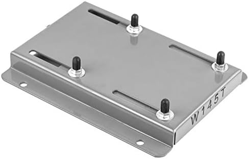
Are there industry standards for the dimensions and specifications of motor slide rails?
Yes, there are industry standards that define the dimensions and specifications of motor slide rails. Here’s a detailed explanation:
The dimensions and specifications of motor slide rails are crucial for ensuring compatibility, interchangeability, and proper functioning within motor installations. Several organizations and industry bodies have established standards that provide guidelines for the design, dimensions, and performance requirements of motor slide rails. These standards help manufacturers, engineers, and users maintain consistency and quality in motor slide rail systems.
1. International Organization for Standardization (ISO):
The International Organization for Standardization (ISO) is a widely recognized international standard-setting body. ISO has developed various standards related to mechanical and industrial components, including motor slide rails. ISO standards such as ISO 4343 and ISO 4344 provide guidelines for the design, dimensions, and performance requirements of linear motion systems, which encompass motor slide rails.
2. American National Standards Institute (ANSI):
The American National Standards Institute (ANSI) is an organization that oversees the development of voluntary consensus standards in the United States. ANSI has published standards related to linear motion systems, which can include motor slide rails. ANSI B5.57 is an example of a standard that covers the dimensional and performance requirements for linear motion systems.
3. European Committee for Standardization (CEN):
The European Committee for Standardization (CEN) is responsible for developing European standards across various industries. CEN has established standards related to linear motion systems, which can include motor slide rails. These standards, such as EN 619 and EN 12090, define the dimensions, performance characteristics, and testing methods for linear motion components.
4. Japanese Industrial Standards (JIS):
The Japanese Industrial Standards (JIS) specify the standards used for industrial activities in Japan. JIS standards cover a wide range of products and components, including linear motion systems and motor slide rails. Standards such as JIS B 8017 and JIS B 8032 provide guidelines for the design, dimensions, and performance requirements of linear motion components.
It’s important to note that the specific standards applicable to motor slide rails may vary depending on the region, industry, and intended application. Manufacturers and users should consult the relevant standards applicable to their specific geographic location and industry sector to ensure compliance and compatibility.
Adhering to industry standards for motor slide rails helps promote consistency, compatibility, and interoperability among different manufacturers and systems. It ensures that motor slide rails meet certain quality and performance criteria, facilitating their integration into motor installations and promoting overall system reliability and safety.
In summary, industry standards established by organizations such as ISO, ANSI, CEN, and JIS provide guidelines for the dimensions and specifications of motor slide rails. These standards help ensure compatibility, interchangeability, and performance consistency within motor slide rail systems across different industries and regions.
editor by CX 2023-10-23
China best Hot Selling SMA 210 270 Adjustable Motor Slide Base and 312/6.8 DHA Motor Rail vacuum pump adapter
Product Description
SMA Common Base:
Characleristics: galvanization finish, with split platesslidling, it’s convenient for bolts fixing of motors.
Application: fixing and adjustment of all series motors.
MP Motor Base:
Characteristics: gavanization fnish WTH MONOPLATE SLIDNG,bending and pressing
Applcatiorne the HangZhoug and adjustment of large power motors.
MB Type Motor Pedestal:
Characteristics: welded with high quality steel, powder coating finish, with matched fixing screw ofmotors, it is much convenient for fixing and adjustment.
Application: Application: suitable for the fixing and adjustment of large,medium and small power motors.
DHA Motor Rail:
it is with unique design, beautiful appearance, steady fixing and powerful weight bearing. It can be widely uesd in the fixing and adjustment of different kinds of motors.
characteristics:
Made of high quality steel with pressing and processing. It is with matched fixing screw of motor, much convenient for adjustment.
Application: the fixing and adjustment of different kinds of motors.
Main Products:
Timing belt pulleys, timing bars, timing belt clamping plates.
Shaft locking devices (assemblies) and shrink discs: could be alternative for Ringfeder, Sati, Chiaravalli, BEA, KBK, Tollok, etc.
V belt pulleys and taper lock bush.
Sprockets, idler, and plate wheels.
Gears and racks: spur gear, helical gear, bevel gear, pinion gear, worm gear, gear rack.
Shaft couplings: miniature coupling, curved tooth coupling, chain coupling, HRC coupling, normex coupling, FCL coupling, GE coupling, rigid and flexible coupling, jaw coupling, disc coupling, multi-beam coupling, universal joint, torque limiter, shaft collars.
Forging, Casting, Stamping Parts.
Other customized power transmission products and Machining Parts (OEM).
| Standard or Nonstandard: | Standard |
|---|---|
| Feature: | Flame-Retardant, Anti-Static, Oil-Resistant, Cold-Resistant, Corrosion-Resistant, Skid-Resistance, Wear-Resistant, Acid-Resistant |
| Application: | Motor |
| Surface Treatment: | Zinc Plating |
| Material: | Carbon Steel |
| Suitable Motor Model: | 63-200 |
| Samples: |
US$ 10/Piece
1 Piece(Min.Order) | |
|---|
| Customization: |
Available
|
|
|---|
How does the selection of motor slide rails impact the overall performance and longevity of motors?
The selection of motor slide rails has a significant impact on the overall performance and longevity of motors. Here’s a detailed explanation:
The motor slide rails play a crucial role in supporting and guiding the movement of motors in various applications. The selection of appropriate slide rails directly affects the performance, efficiency, and lifespan of motors. Here are some key factors to consider:
1. Precision and Accuracy:
The selection of motor slide rails with high precision and accuracy is essential for achieving smooth and precise motor movement. Slide rails with tight tolerances and minimal play minimize backlash and vibration, resulting in improved motor performance. Precise slide rails ensure accurate positioning of the motor, which is critical in applications that require precise control or alignment. Choosing slide rails with high precision can enhance the overall performance and reliability of motors.
2. Load Capacity:
The load capacity of motor slide rails is an important consideration to ensure that the rails can support the weight of the motor and any additional loads. Using slide rails with insufficient load capacity can lead to premature wear, excessive deflection, or even failure of the rails, resulting in compromised motor performance and potential safety hazards. It is crucial to select slide rails that can handle the anticipated load requirements to maintain optimal motor performance and longevity.
3. Durability and Materials:
The durability and materials of motor slide rails directly impact their longevity and ability to withstand demanding operating conditions. Slide rails made from high-quality materials, such as stainless steel or aluminum alloys, offer better resistance to corrosion, wear, and environmental factors. Additionally, slide rails with appropriate surface treatments or coatings can provide enhanced protection against abrasion, chemicals, or extreme temperatures. Choosing durable slide rails ensures long-term performance and reliability of motors, especially in applications with harsh environments or heavy usage.
4. Friction and Lubrication:
The selection of motor slide rails with appropriate friction characteristics and lubrication requirements is crucial for optimizing motor performance and longevity. Excessive friction between the slide rails and motor can result in increased energy consumption, reduced efficiency, and accelerated wear. Conversely, insufficient friction may lead to instability or inadequate load support. The type and amount of lubrication required for the slide rails should be considered to minimize friction, reduce wear, and maintain smooth operation. Proper lubrication practices help extend the lifespan of both the slide rails and the motor.
5. Environmental Considerations:
The operating environment can significantly impact the performance and longevity of motors and slide rails. Factors such as temperature extremes, humidity, dust, moisture, or exposure to chemicals can affect the materials, lubrication, and overall functionality of the slide rails. It is important to select motor slide rails that are specifically designed or rated for the anticipated environmental conditions. Slide rails with appropriate seals, coatings, or protective measures can enhance their resistance to environmental factors, ensuring reliable motor performance and longevity in challenging environments.
6. Application-specific Requirements:
Each motor application may have unique requirements that affect the selection of slide rails. Factors such as speed, acceleration, deceleration, shock resistance, or vibration tolerance should be considered to ensure the slide rails can meet the demands of the application. Additionally, compatibility with other components, such as mounting brackets or accessories, should be evaluated to ensure proper integration and optimal performance. Selecting motor slide rails that align with the specific requirements of the application can enhance motor performance and longevity.
In summary, the selection of motor slide rails has a significant impact on the overall performance and longevity of motors. Considerations such as precision and accuracy, load capacity, durability and materials, friction and lubrication, environmental considerations, and application-specific requirements are essential when choosing slide rails. By selecting appropriate slide rails, users can optimize motor performance, ensure reliable operation, and extend the lifespan of motors.
Can motor slide rails accommodate various motor mounts and couplings?
Yes, motor slide rails are designed to accommodate various motor mounts and couplings. Here’s a detailed explanation:
Motor slide rails are versatile components that can be integrated into motor installations with different types of motor mounts and couplings. They are designed to provide a universal platform for mounting motors, allowing for flexibility and compatibility with a wide range of motor configurations.
1. Motor Mounting Options:
Motor slide rails are typically designed with multiple mounting options to accommodate different motor mounts. These mounting options can include slots, holes, or threaded inserts that allow for the attachment of various motor mounting brackets or plates. The flexibility in motor mounting options enables the use of different motor mount designs, such as foot mounts, flange mounts, or face mounts. Motor slide rails provide a secure and adjustable interface for connecting the motor mounts to the rail system.
2. Coupling Compatibility:
Motor slide rails can also accommodate various types of motor couplings. Motor couplings are used to connect the motor shaft to the driven equipment, such as a gearbox or a load-bearing mechanism. Different types of couplings, such as flexible couplings, rigid couplings, or torsionally flexible couplings, have specific dimensional requirements and attachment methods. Motor slide rails are designed to provide sufficient space and clearance for the installation of different types of motor couplings. They allow for easy integration of the coupling components, ensuring proper alignment and connection between the motor and the driven equipment.
3. Adjustable Mounting Positions:
One of the key advantages of motor slide rails is their adjustable mounting positions. They provide a range of positions along the rail where the motor can be secured. This adjustability allows for fine-tuning the motor position and aligning it with the driven equipment or other components in the system. The ability to adjust the motor position using the slide rails accommodates variations in motor mount dimensions and facilitates precise alignment of the motor and coupling.
4. Customization and Adaptability:
In some cases, motor slide rails can be customized or adapted to specific motor mount or coupling requirements. Manufacturers may offer options for modifying the dimensions, hole patterns, or attachment methods of the slide rails to suit unique motor mounting or coupling configurations. This customization ensures compatibility and ease of integration with specialized motor systems or applications.
Overall, motor slide rails are designed to be versatile and adaptable, allowing for the accommodation of various motor mounts and couplings. The multiple mounting options, compatibility with different coupling types, adjustable mounting positions, and potential for customization make motor slide rails a flexible solution for motor installations across a wide range of industries and applications.
In summary, motor slide rails are capable of accommodating various motor mounts and couplings. Their design incorporates multiple mounting options, compatibility with different coupling types, adjustable mounting positions, and potential for customization, ensuring versatility and compatibility with different motor configurations.
Can motor slide rails be used for both horizontal and vertical motor installations?
Yes, motor slide rails can be used for both horizontal and vertical motor installations. Here’s a detailed explanation:
Motor slide rails are versatile components that provide flexibility in motor positioning and alignment. They are designed to accommodate various installation orientations, including both horizontal and vertical configurations. The adaptability of motor slide rails allows them to be used in different orientations to suit the specific requirements of the motor and application.
Horizontal Motor Installations:
In horizontal motor installations, the motor slide rails are typically mounted on a base or mounting platform. The motor is then positioned on the rails and secured in place. Horizontal motor installations are commonly used in applications where the motor shaft needs to be parallel and co-linear with the driven equipment. The motor slide rails facilitate precise alignment, allowing for horizontal adjustability to achieve the desired alignment. Horizontal motor installations are prevalent in many industrial and commercial applications.
Vertical Motor Installations:
In vertical motor installations, the motor slide rails are used to support and position the motor vertically. The rails are mounted vertically on a base or mounting structure, and the motor is slid into position along the rails. Vertical motor installations are typically employed in applications where space is limited, and it is more practical or efficient to position the motor vertically. Vertical motor installations are common in situations such as pump systems, hoists, or machinery where a compact footprint is desired.
Motor slide rails designed for vertical installations may have additional features to ensure the motor’s stability and secure placement. These features can include locking mechanisms, anti-vibration pads, or other components to prevent the motor from shifting or rotating while in operation.
Whether used for horizontal or vertical motor installations, motor slide rails offer several benefits. They allow for easy motor installation and removal, precise alignment, vibration damping, maintenance accessibility, and flexibility in motor positioning. Their versatility in accommodating different installation orientations makes them suitable for a wide range of applications, providing the necessary adaptability to meet specific motor and system requirements.
In summary, motor slide rails can be used for both horizontal and vertical motor installations. They are designed to provide flexibility and ease of use in positioning and aligning motors, regardless of the installation orientation. The choice between horizontal and vertical installation depends on the specific application, space constraints, and the desired alignment and performance objectives.
editor by CX 2023-10-20